Build of Gray Hoverman UHF Antenna
Why would anyone even want to build their own UHF television antenna?
Assuming you get your television "over the air", i.e. from an antenna, then after the transition to digital television, sometime after February 17, 2009, channels 2,3,4 and 5 will cease transmitting on their old frequencies in the VHF band (approx 52-76MHz) and will start transmitting on new channel assignments in the UHF Band. For example, in the NY Metro area, that means that channels 2,4, and 5 will now be at UHF channels 33, 28 and 44. So even if you never had any interest in UHF before, if you like watching WCBS, WNBC, or FOX television from NY City, you'll need to be interested in UHF now. Note that these reassignments are true nationwide, though the actual UHF frequency that 2,3,4 and 5 will be reassigned to depend on what other channels exist in that market.
Note: Channels 2,3,4, and 5 may not be re-assigned in every market.
I live in the "fringe" area for reception, 44 miles from NYC and 51 miles from Philadelphia, and with a decent-sized commercial UHF antenna with pre-amp, I still couldn't reliably get digital channel 3-1 (really UHF channel 26) from Philadelphia. I decided to build the Gray-Hoverman antenna after seeing the published simulation results.
Compared with my previous antenna, I found that channel 3-1 from Philadelphia came in with a noticably stronger signal.
Please note that fringe television reception is very tricky. If you're 50 miles out, then the amount of signal you will lose due to leaves on trees (more signal in winter than in summer), and rain and snow fade can mean the difference between a watchable signal and not. Further, you must mount your antenna as high as you can, with a good view of the transmitter tower (i.e. not behind a tall building or a mountain). Finally, you'll probably want an antenna pre-amplifier so you can overcome the loss in the cable that runs from the antenna to your television.
Note also that if you fall off your roof or electricute yourself brushing your ladder against a power line, I take no responsibility for this. You shouldn't be up on your roof fooling around if you don't know what your doing. Just pretend you never saw this article.
To see what size antenna you will need to pick up over the air television signals, go here. In general, if you're 25 or more miles out, a rabbit ears on the top of your set won't cut it.
The plan and performance information for this antenna was originally published here.
I'm considering offering kits of pre-cut PVC pipe, pre-bent copper wire, hardware cloth or chicken wire for the reflector (back), and miscellaneous screws and hose clamps, if there is sufficient interest. See the bottom of this page for more information.
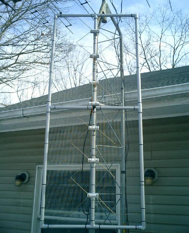
Here's what my build of it looks like. You can see that I copied one of the examples shown on the digitalhome.ca website.
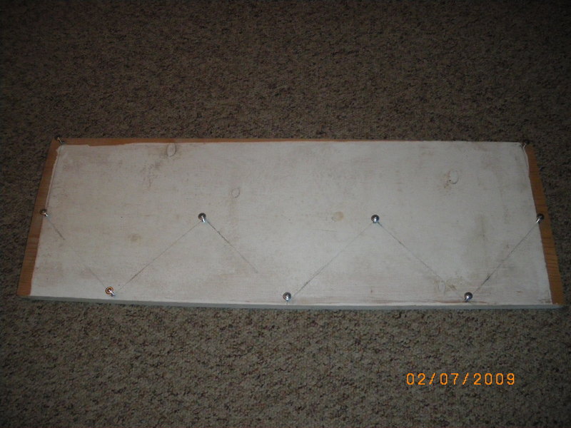
Here's my jig for bending the element wire. Since, for a dual bay antenna, you need four elements, I thought it worthwhile to make a dedicated jig.
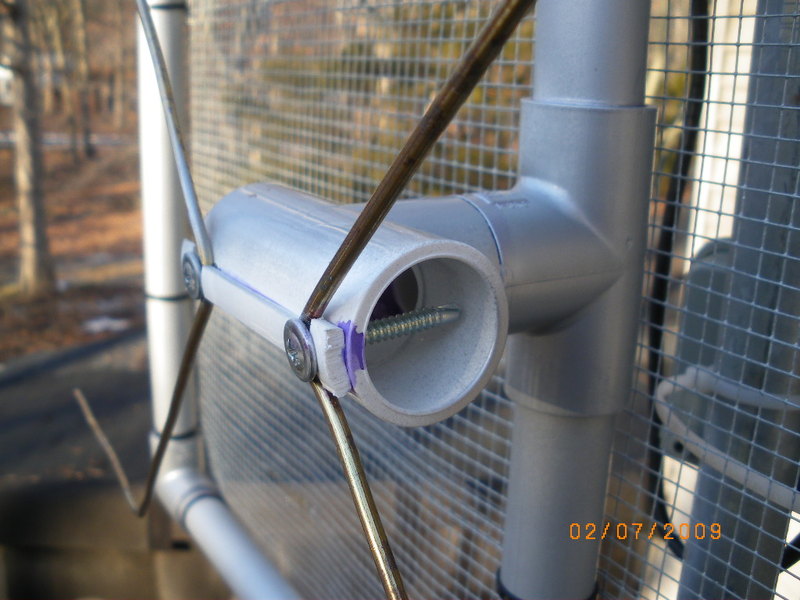
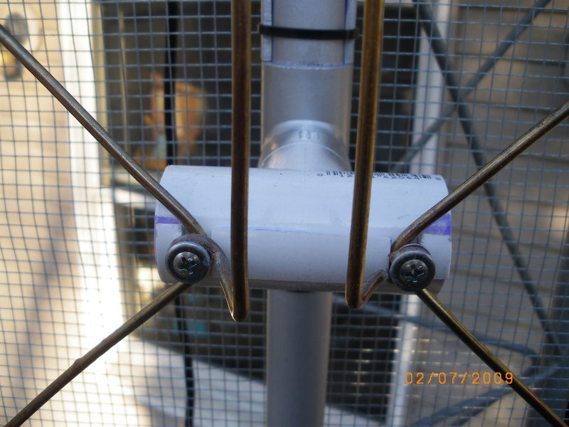
A close-up of one of the element supports. Notice the fiddly little bits of PVC glued on to keep the wire located under the screw head.
The tee with the screws in it has been shortened by about 3/16 inch so that the total distance from the back surface to the surface the element wires mount to is exactly 100 mm (about 3 15/16 inch).
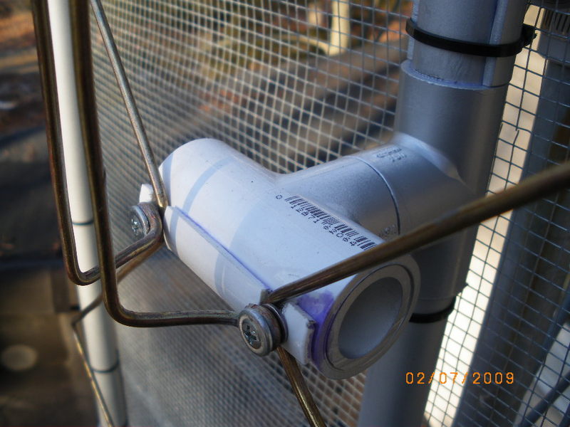
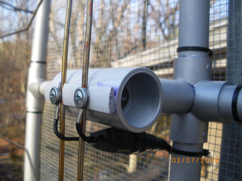
This is the output of a single bay. Since this is a dual bay antenna, there are more heavy copper wires going from here to the matching spot on the upper bay. If you're only building the single bay version, then this is where you would attach the matching transformer to which your coax cable connects.
You may notice a small stub of PVC pipe inserted in this tee. This is to give more "meat" for the screw to bite into, to make the attachment of the wires more secure. I did this on the tees that had more than one wire under each screw. It's possible that this is overkill.
Another view of the output of the lower bay.
This is the center point of the wires interconnecting the two halves of the dual bay antenna. The matching transformer converts the 300-ohm output to the 75-ohm impedance of the coax cable.
The cross in the center of the antenna has been drilled to accept a piece of 3/4 inch PVC, because they don't make 5-way PVC junctions. The distance from the back to the front should be 130 mm here.
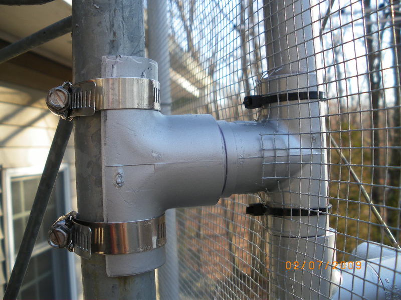
This is one of the two mounts from the antenna to the mast. The tee that is hose-clamped to the mast is a 1-inch PVC tee, with a reducer that takes it down to 3/4-inch PVC to connect to the antenna spine.
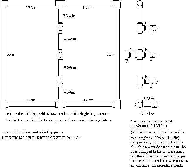
This is a schematic of the PVC pipe framework for a single bay. The lengths of PVC are purposely shorter than calculations would suggest so that you don't have to get the PVC joints to fully seat. When you assemble it, you only push the joints in sufficiently to get the distance between screw locations correct, per the plans on the digitalhome.ca web site.
Parts list for single bay antenna:
- 12 feet #8 solid copper wire
- 2 10 foot lengths 3/4-inch PVC pipe
- PVC primer and cement
- 4 90-degree 3/4-inch PVC elbows
- 2 3/4-inch PVC crosses
- 6 3/4-inch PVC tee
- 2 PVC tee (and reducers if needed) sized to fit your mast diameter
- 4 hose clamps to fit around the above tee
- enough chicken wire to cover 30x36 inch rectangle
- 6 "MOD TRUSS SELF DRILL ZINC 8x1-1/4" screws
- a handful of tie-wraps to attach the chicken wire
- spray paint if you don't want it to look like PVC pipe
Parts list for dual bay antenna:
- 25 feet #8 solid copper wire
- 3 10 foot lengths 3/4-inch PVC pipe
- PVC primer and cement
- 4 90-degree 3/4-inch PVC elbows
- 3 3/4-inch PVC crosses
- 15 3/4-inch PVC tee
- 2 PVC tee (and reducers if needed) sized to fit your mast diameter
- 4 hose clamps to fit around the above tee
- enough chicken wire to cover 30x72 inch rectangle
- 14 "MOD TRUSS SELF DRILL ZINC 8x1-1/4" screws
- a big handful of tie-wraps to attach the chicken wire
- spray paint if you don't want it to look like PVC pipe
Possible long-term reliability problems with this design:
- The tie-wraps may fail due to UV exposure.
- The copper wire used for the elements may corrode and fail.
- The chicken wire will eventually rust and look ugly and fall off.
Painting these items is likely to increase their longevity.
Availability of kits
There has not been sufficient interest to warrent offering kits.
If you have questions about the kit (like substitutions of materials) you can try emailing me here.
Question: what kind of material can I make the reflector out of?
The best material is the best conductor. The best conductors are, in order: silver, copper, aluminum, and then other metals (steel, etc).
The reflector does not need to be solid but the holes in it need to be small in relation to the shortest wavelength that will be received.
The shortest wavelength is the highest frequency, which is channel 69, about 806MHz. The wavelength of 806MHz is about 35cm or 13.6inches.
So the holes in your reflector should be small with respect to 13.6 inches. By "small" I would suggest 1/10 of 13.6 inches, so that would suggest 1.3 inch "holes" are allowable.
So the upshot is that chicken wire or other wire fencing should work fine. Aluminum window screen would be good. The only reason to avoid something solid is wind load. If the antenna is indoors then wind load is not an issue and you can use aluminum foil or even an aluminized mylar balloon.
This page Copyright © 2009,2013 William F. Dudley Jr.
The Gray-Hoverman antenna designs, schematics, and diagrams on this site are Copyright © 2008 and are free: you can redistribute them and/or modify them under the terms of the GNU General Public License as published by the Free Software Foundation, either version 3 of the License, or (at our option) any later version.
These designs, schematics, and diagrams are distributed in the hope that they will be useful, but WITHOUT ANY WARRANTY; without even the implied warranty of MERCHANTABILITY or FITNESS FOR A PARTICULAR PURPOSE. See the GNU General Public License for more details.
For your complete copy of the GNU General Public License to go along with the designs, schematics, and diagrams, see www.gnu.org/licenses/gpl.txt.


 Views
Views