Anti Wet-Sumping Valve for Motorcycle, with Electrical Interlock
My Norton Commando occasionally wet sumps, i.e. some of the oil from the tank drains down into the engine sump. This is a bad thing. There are several ways of dealing with this:
- Ignore the problem, and perhaps drain the sump and pour it back into the oil tank before each ride.
- Install a "ball check" anti sumping valve. This uses a steel ball held against a seat by a weak spring. The hope is that the spring is strong enough to overcome the force of gravity wanting to move the oil down into the sump, but weak enough that the oil pump suction can overcome it when the motor is running. Many folks use these, and probably an equal number distrust them. I have used one but don't like it.
- Install a proper valve to shut off the oil flow from the tank. The problem here is that if you forget to turn the valve on before starting your motor, you'll destroy the motor. How can one make sure the valve is turned on when the bike is running?
My solution (not original) is to mount a microswitch on the valve, so that when the valve is off, no electricity flows to the ignition. For extra credit, the circuit could be wired so that when the bike is off and the valve is on, a warning light is on, reminding you to turn off the valve. I wired the "unused" normally closed contact to a flashing red LED, so I have a clear indication that the ignition circuit is not powered.
I looked, and couldn't find a commercial offering that solves this problem.
Note: Click on the pictures to embiggen.
The first two photos shows my prototype valve with attached microswitch. The switch mounting was machined out of 1" by 1" aluminum bar stock.
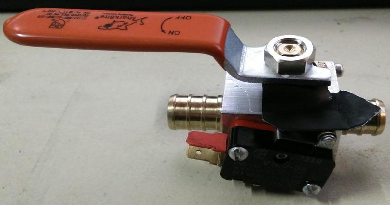
Valve, top view.
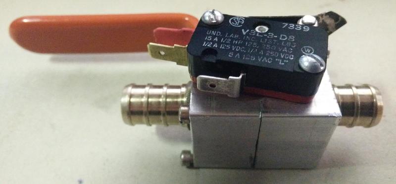
Valve, bottom view.
The third photo shows the bare valve as purchased from Lowes home improvement store, along with the 3-D printed (revision 1) versions of the switch mounting "blocks".
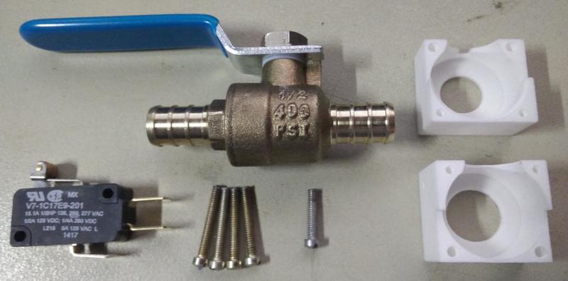
Bare valve from Lowes, microswitch, and 3-D printed switch mounting blocks (version 1.1).
The fourth photo shows the assembled valve/switch with the 3-D printed stainless steel pieces.
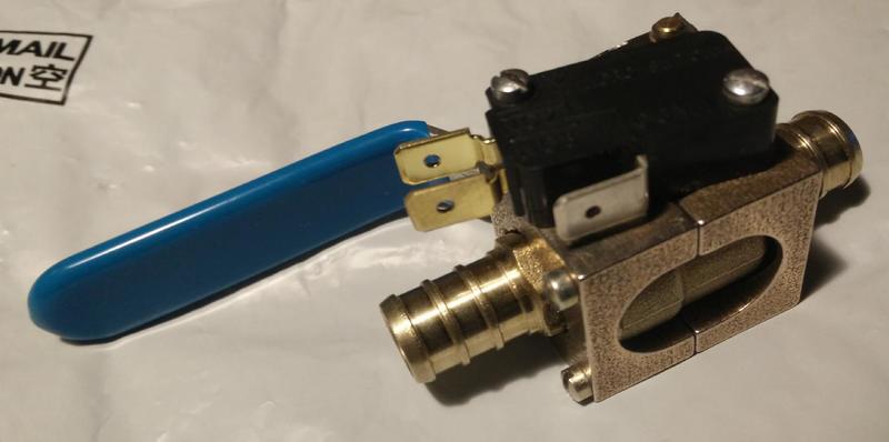
Assembled version with stainless steel 3-D printed switch mounting blocks.
The microswitch is an Honeywell V7-1C17E9-201, which can be bought for $2.82 in onsies from mouser.com. There is also a "second source", the SUNS V-15G5. (The microswitch shown on the prototype is an older version of the same switch, sourced from my junk box.)
The "flag", which actuates the microswitch, is a bit of thin (.020") scrap steel. I have an openscad drawing for this and will either publish that file OR have the flag produced by bigbluesaw.com if I go into "production". The price from bigbluesaw is $2.00 each if I buy 50, $9.98 each if I buy 10 of them. (The chosen material is stainless steel T304, 0.018 inches thick.)
The Problem
Here's the problem: The 3-D printer plastic is only good for 80°C / 176°F. (I'm using shapeways.com to do the printing.) In plastic, these parts only cost $5.10 and $5.35 to produce. I think the valve temperature will exceed 80°C when the Norton's oil is up to "full" temperature, which I imagine is nearer 100°C. So the parts are cheap, but will probably melt or at least distort in use.
In stainless steel, they're $19.27 and $21.69, and that's the cheapest metal they can print. The maximum temperature for stainless steel is 831°C / 1528°F. So these are pricy but will work.
Once I have perfected the design files for the 3-D printer, if I can't figure a way to way to have these printed inexpensively, I may just put the cad files here for download, so people can use them to machine their own housings. I'll also probably leave them on shapeways.com, so people who have the money but not the time (or machine shop) can have them printed in stainless steel.
Parts cost right now is (ignoring sales tax):
| Parts List | |||||||||||||||||||||||||||||||||
|---|---|---|---|---|---|---|---|---|---|---|---|---|---|---|---|---|---|---|---|---|---|---|---|---|---|---|---|---|---|---|---|---|---|
|
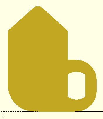 "plan view" of the flag |
||||||||||||||||||||||||||||||||
Tools needed
- 4-40 taps (both a "plug" and a "bottoming" tap) & tap wrench
- #43 drill (may be needed to "adjust" the size of the 3-D printed holes)
- sheet metal shears
- drill and bits to make 5.1 mm hole in the "flag"
- file to finish control shaft hole (for double flatted shaft)
- small screw driver to match 4-40 screws
- 12mm wrench to remove and replace valve handle
- pliers to bend the "flag" to shape
- thread locking compound for all threaded fasteners (12mm nut and 4-40 screws)
comments? Email bill at dudley . nu
Make your own
This is preliminary.
Check that the smaller holes (that will be tapped) are #43 drill sized, drill them if needed. You don't want to break a tap.
Run a 4-40 tap through the two blind holes in each half, and then through the two microswitch mounting holes, one in the side of each half block. The blind holes can benefit from the "bottoming" tap to get the threads all the way to the bottom of the hole. Start all the threading with the plug tap, finish the blind holes with the bottoming tap.
Screw the two halves together around the valve body, using 4 4-40 screws. Screw the microswitch to the side of the mounting blocks using two more 4-40 screws. Make sure those 4-40 screws are the right length so they don't run into the valve body. I had over-long screws that I shortened with a Dremel and cut-off wheel. Put thread locking compound on all the screws, once you're sure that everything fits together correctly.
Remove the nut that attaches the handle to the valve with a 12mm wrench. Remove the handle and the paper-like tag. Put the flag on the valve stem, then the handle, and finally replace the nut and tighten it. For extra security, you might want to put some medium thread locking compound on the threads before you put the nut on.
Bend the flag so that the microswitch actuates when the valve is almost fully open. The closer to fully open the valve is when the microswitch actuates, the better this will work. If the microswitch actuates when the valve is only half-open, then the possibility exists that the motor can be running with the oil line half blocked.
Installation
Drain the oil tank, or clamp off the hose so the oil doesn't run out when you cut the hose. Cut the oil-tank-to-engine oil feed line and remove approximately 1 1/2" (on a Norton twin engine, this is the outer oil line on the crankcase junction block) and fit the valve in the line.
The switch is only rated a .5A DC, so you should either use it to just control your ignition circuit, OR use it to control a bigger relay (like a 20A "horn" relay) that in turn can switch the entire electrical system on or off.
Remove the wire from the ignition switch that feeds the ignition (coil) circuit. Connect this wire to the "NO" terminal on the microswitch. Run a new wire from the ignition switch terminal just vacated to the "COM" terminal on the microswitch. Now, when the oil valve is ON, the microswitch is "ON", and the ignition circuit is powered as usual (when the key is on).
For extra credit, wire an LED (in series with a current limiting resistor; about 1000 ohms) across the COM and "NO" terminals on the switch. Locate the LED near your instrument pods. Now, when the oil/switch is off, but the ignition is on, you'll have a warning LED showing you that the bike won't run as the oil is off. This should prevent you kicking fruitlessly with the oil (and ignition) off.
LED wiring instructions: (positive ground) the cathode (-) side of the LED connects to the power source side of the micro-switch. The anode side (+) connects to the 1K resistor. The other side of the resistor connects to the ignition circuit (the coils or the electronic ignition module).
FAQ
1. What if the switch breaks? Am I stranded?
No, you're not stranded: just connect the two wires that go to the switch together and you can continue your ride.
Disclaimer
Realize that if you undertake to build and install this, you do so entirely at your own risk. If you blow up your motorcycle, you will be unhappy.
William Dudley
November 19, 2017


 Views
Views