Burglar Alarm System
I had a "brand name" burglar alarm system installed in this house many years ago, but when I switched my phone system to use VOIP over my internet, the phone connection to the alarm system was disconnected and it was too much bother to re-route the phone system to accomodate the alarm system. In addition, I wasn't too wild about the $30/month monitoring fee, and also the fact that the system relied on the phone system. Wouldn't an internet enabled alarm be "better"? It could text me, email me, and be easier to control. Time to whip out another Arduino.
My Arduino projects always end up blowing past the 22K code limit of the Uno, and this was going to need a bunch of I/O anyway, so clearly the Arduino Mega 2560 is the board to use. I hooked this up to the following stuff:
- Seeed Studio Ethernet shield
- ESP8266 Wifi board (back-up internet connection)
- DS3231 Battery Backed-up Clock (in case NTP is unavailable)
- switching buck regulator 12v to 9v (two)
- Relay (for the alarm bell)
- LCD with serial interface (4x20) (front panel)
- LCD with IIC interface (4x20) (secondary panel)
- Digital Pot (front panel digit entry>
- Analog pot (secondary panel digit entry>
- 4 Key membrane keyboard (two, one for each panel)
- Adafruit Sound Effects Board
- Class D 12VDC Stereo Amplifier
- Ground loop isolating transformer (between SFX board and Amp)
- In-line stereo volume control (also between SFX board and Amp)
- Ming Engineering Wireless Radio Receiver with two transmitter "fobs"
- X10 FireCracker Wireless transmitter
- Arduino Mega-compatible screw terminal shield with prototyping area
- Custom circuitry to isolate the Arduino inputs from the alarm contact wiring
- Custom circuitry for watchdog timer
- Custom circuitry for Arduino programmed self-reset
- USB B Male to Female extension cable
- Ethernet extension cable
Note: Click on the pictures to embiggen.
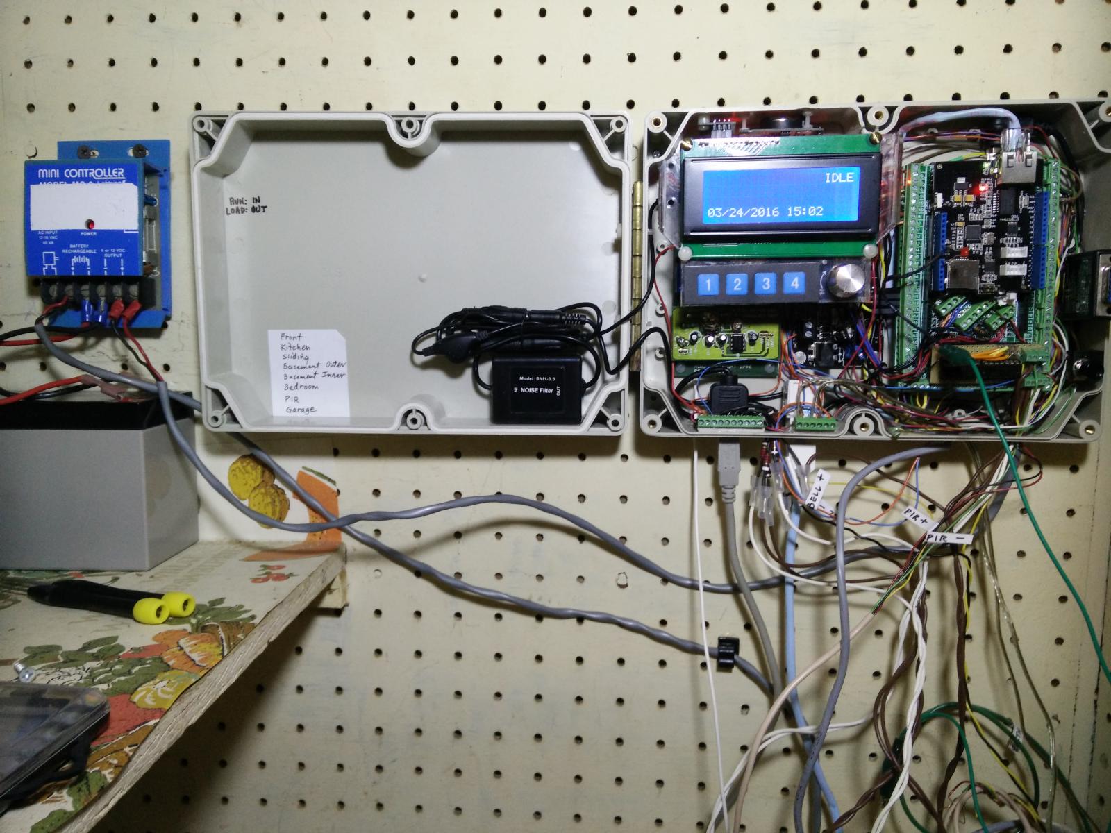
The system installed in its closet.
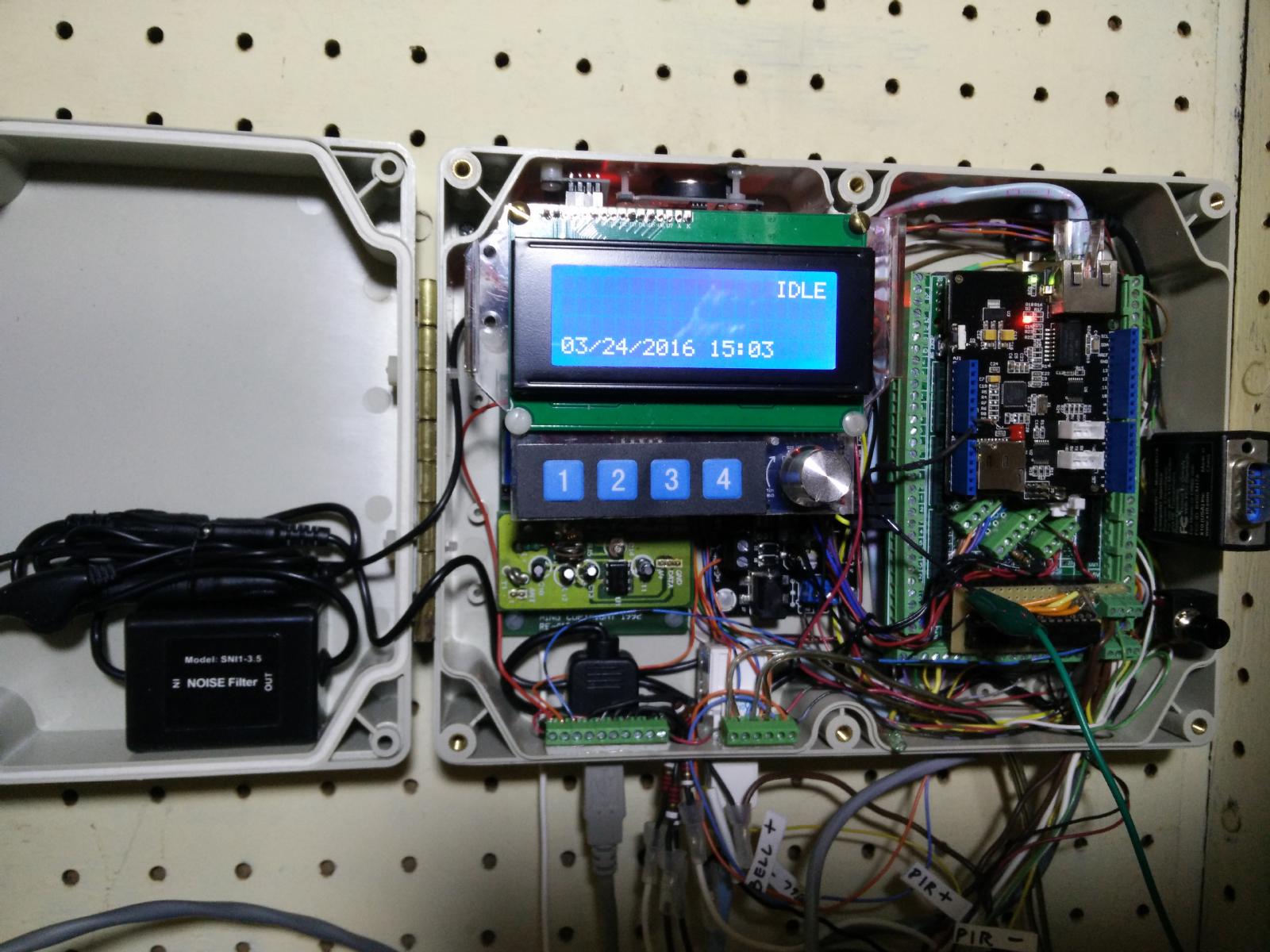
Close-up of the system in it's enclosure.
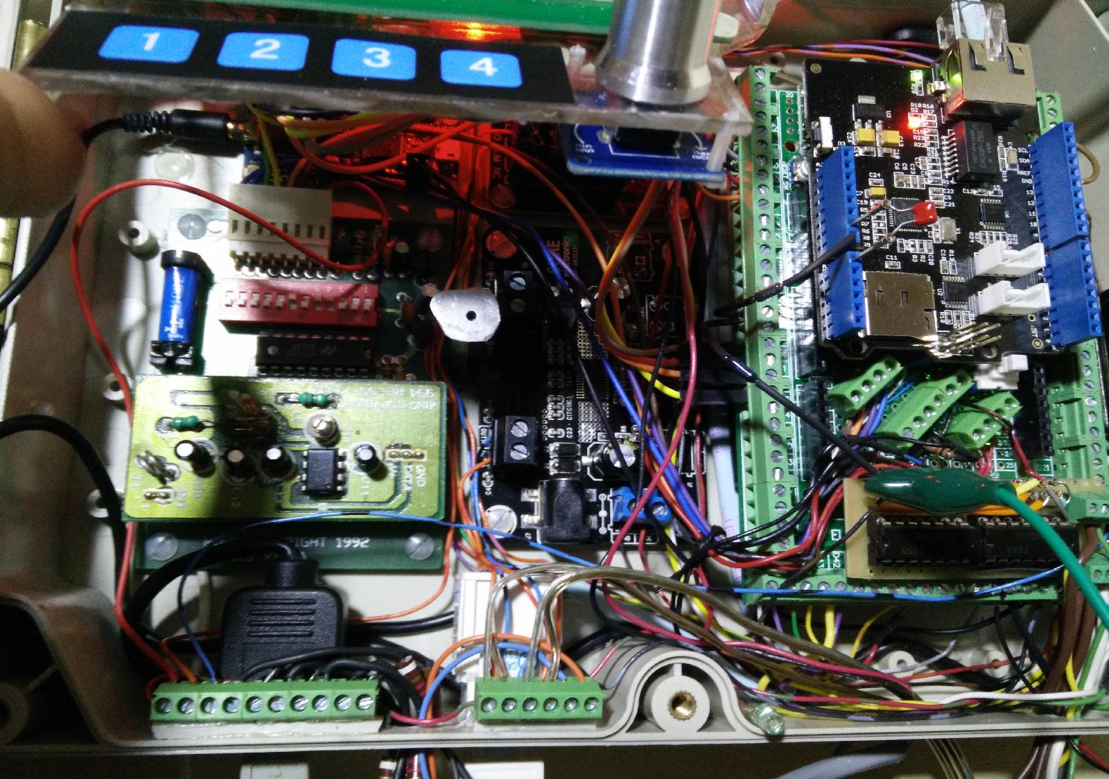
Close-up of modules under the flip-up front panel.
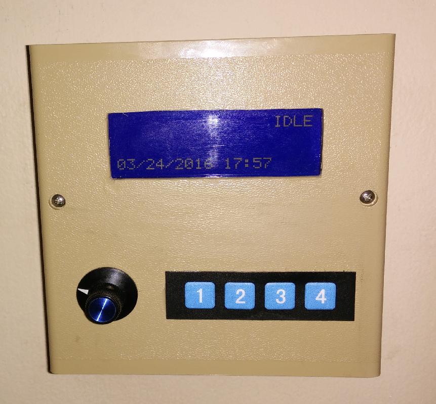
The "main" front panel.
The system has the following features:
- It gets the current time and date via NTP.
- It's programmed to understand daylight savings, and knows when sunrise and sunset are, for every day of the year.
- Alarm can be armed and disarmed via either panel, or using wireless "fob".
- Turns house lights on at dusk, off at bed time and/or dawn using X10.
- It turns on the interior lights if the exterior door opens when it is alarmed, if the time is between dusk and dawn.
- Has a web page to allow configuration changes (internet parameters, X10 parameters and scheduling). Configuration parameters are kept in EEPROM.
- Web interface cannot arm and disarm the system, nor can configuration changes be made when the system is armed.
- Alarm system plays sound effects as needed; barking dogs when armed and somebody enters the house, for example.
- Alarm system sends email to as many people as I want when an alarm condition occurs. Email includes use of email to text gateway, so that I can get a text in the case of an alarm.
- Alarm has automatic "night time" mode that only monitors the exterior doors, starts "dogs barking" sound effect if doors opened at "night".
- It keeps a log in EEPROM of "state changes", meaning whenever the system is armed or disarmed. The log can be viewed from the web or from either panel.
- The system keeps track of "uptime" and can report same via web and front panel.
- The system operates off of a 12 v battery which is in turn kept charged by a "float" charger.
- The system can report battery voltage via front panel and the web page.
Random Notes on the Design
On each of the main Arduino and also the remote front panel, a small switching regulator drops the 12v to 9v which is then fed into the Arduino's on-board regulator to be dropped to 5v. This additional regulator is so that the Arduino's on-board regulator won't overheat, as it would were it dropping from 12v to 5v.
I haven't had the best success using the on-board watchdog timer in the Arduino chips. For this project, I wired up my own watchdog timer, using (what else?) a 555 timer and some loose gates wired to enable or disable the watchdog. Another 555 timer acts as a one shot pulse generator, so that the Arduino can give itself a reset should it determine that the hardware (mainly the Ethernet interface) needs a hardware reset. See Here for full details on this.
The wires from the door switches can be quite long, running the length of the house. They can pick up electrical noise (spikes) that might damage the Arduino if connected directly to the Arduino's digital inputs. In order to protect the Arduino's digital inputs, I buffer the contact signals by running each of them through an open collector transistor. For packaging efficiency, I use two dip packages containing 5 open collector transistors each. More about the buffers here.
When I connected the Adafruit Sound Effects (SFX) Board to the audio amplifier, there was an annoying level of buzz. This was due to the shared power supply grounds forming a ground loop with the digital and analog ground connections between the devices. To eliminate this buzz, I installed a ground loop isolation transformer between the SFX board and the amplifier board. These are often sold for car audio applications, and not terribly expensive. That's the black lump that's glued into the cover of the box (shown in the photos above).
I ended up with little boards shoved everwhere in the project box I chose. Were I to do this over again, I probably should choose a bigger box. Failing that, I used hinged standoffs to mount the board holding the secondary front panel, so that it can be hinged up out of the way to get to the boards underneath it. A magnet hold it in the "down" position at other times.
I used a digital pot for the front panel because I'd had the thing in my junk box for decades and got tired of looking at it doing nothing. I used an analog pot in my secondary front panel because I only had one digital pot. The analog pot was a bigger pain in the neck, due to the inherent jitter in reading the value. I had to add some hysteresis in software.
The remote front panel has an Arduino Pro-mini in it, that acts as a serial interface for the 4x20 LCD, plus it scans the 4 keys and the digital pot, and transmits those codes over the serial line back to the Arduino. Someday I'll document that front panel, but for now, you're on your own.
During development I had two units working at once, so I could make hardware changes to one while the other one was getting new software tested. Even after installing the "final" hardware I'm still using the second unit to test new software ideas, though this is happening less now that I'm running out of features to dream up. I'm also running out of bugs to fix.
Building it
Here is the connection list for the I/O.
Here is the schematic and discussion of the custom circuitry (the watchdog timer, etc) in the alarm system.
Here is a tarball of the code. The code has been updated as of 2018 January 03.
Customization
Not everything is customizable via the web interface (pure laziness on my part). You'll probably want to change the names of the alarm "zones" in the source code (i.e. "Front Door", "Kitchen", etc.) You'll also want to set the wifi SSID and password, the alarm entry/exit codes, and the IP address stuff, though that last can be changed from the web page if you boot in DHCP mode.
The X10 stuff is all customizable via the web interface, but I have the unit initialize itself on first run by naming all the X10 stuff with my "lamp" names and putting in my schedule. You may find it easier to either delete all my initialization of the X10 stuff, or change it in the source code to match your X10 installation.
Ditto the ethernet interface, which I initialize to my network parameters, but you can change this from the web interface. (There is also a button you can press during boot up that will cause the code to use DHCP to get network parameters, so no other changes are needed if you press that button during first boot. It's highly recommended that you monitor the debug output of the unit during initial boot so you can watch the success or failure of the network stuff.
The wifi parameters are in EEPROM but the web interface is tricky. You don't want to expose the SSID and password in a web page unless your web page has authentication, and mine doesn't. So I don't show the SSID and password values in the web page, but I do allow you to change them from the web page. This works, but doesn't allow you to set the ssid or password to "****" (not a problem in my opinion). (There is a debug mechanism: if the "second unit switch" is closed (low) then the web interface will show the current values of ssid and password.)
Installation
Attach a computer to the USB cable during boot with the Arduino serial monitor window open (115200) so you can watch the boot process. If the boot is totally successful (DNS works, NTP works) then the "DNS OK" LED will light up. If you want, you can hold down the "USE DHCP" button during boot and the unit will attempt DHCP rather than use the canned IP address and other network parameters. Once the unit has run a few (5?) minutes, it will write the new configuration to EEPROM, so from then on, the unit will boot with those parameters and a "static" IP address, and you need not hold down the DHCP button again during boot.
The "USE DHCP" button has another function. Pressing it and hitting the "clear" button (#2) on the main unit's front panel will cause the uptime and battery voltage to display on the LCD until the next LCD update. Pressing it will also invert the state of the "DNS OK" LED, so you know the button is being monitored and the code is running.
The alarm loops are wired from +12V and return to the alarm system input pin, with a 2.2K resistor in series with (and "before") the alarm loop. That way a short on the alarm loop won't short out the 12V battery. The Arduino code is written so that the loop is "closed" (door or window closed) when the digital input is low, but this can be inverted in software if you want to roll your own input circuitry.
FAQ
Q. Why can't I arm or disarm the unit from the web page?
A1. Because then somebody connecting to your wifi from outside the house can turn off your alarm system.
A2. Actually, you can arm and disarm from the web, but you have to read the source code to find out how, as there's no "link" or "button" to press. I built this in as a "not super secure but sure to keep out your average junkie" method that a phone app could use to arm/disarm the system.
Q. Is there code for the remote front panel?
A. Yes sirree, bob, right here. The front panel is a 9600 baud serial device. Four push buttons and a digital pot send characters to the main unit, and the main unit updates the LCD as needed.
Disclaimer
Don't blow up your house, kiddies. Most of this project is safe stuff, except for the 12V battery, which can be dangerous if shorted out. Don't let your silver bracelet bridge the terminals when you're working on it, OK?
Track Back
William Dudley
March 28, 2016
revised January 5, 2018


 Views
Views