Making a Case from Garbage
Having solved the hardware and software for the Z5300 Remote Control, I needed to put it in a case. I have a good stock of plastic and metal project cases, but the only one that was about the right size was the case from a dead thermostat that I'd harvested when the thermostat died (years ago).
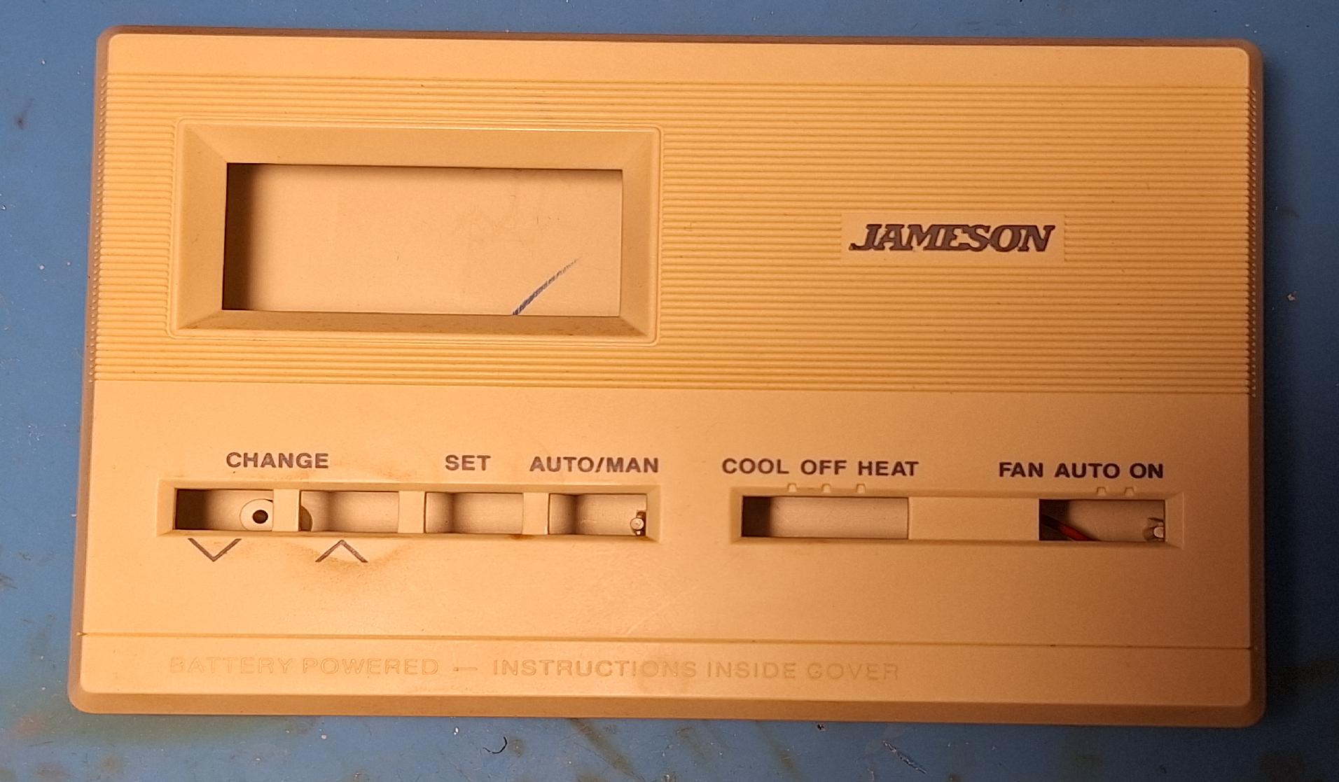
The old thermostat case.
The thermostat case is too big (tall) and has a bunch of holes I don't want, so I ran it through a band saw and sliced out a section.
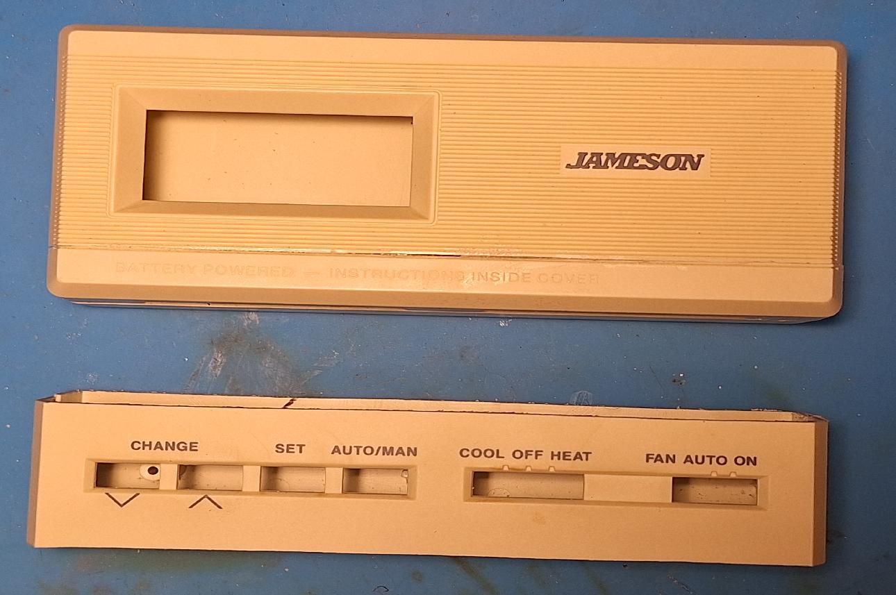
I've cut the case down and glued the top and bottom together. Looks better already. The piece below will supply plastic scrap for the rest of the work.
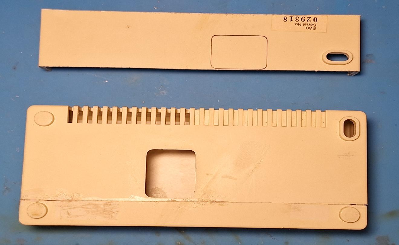
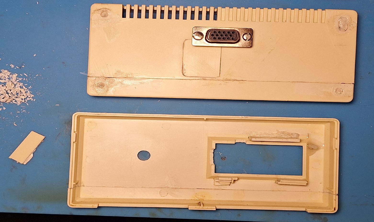
Here's the back of the cut down case. It's got a hole in the wrong place, so I've identified a piece of the cut off that will be used to fill the hole.
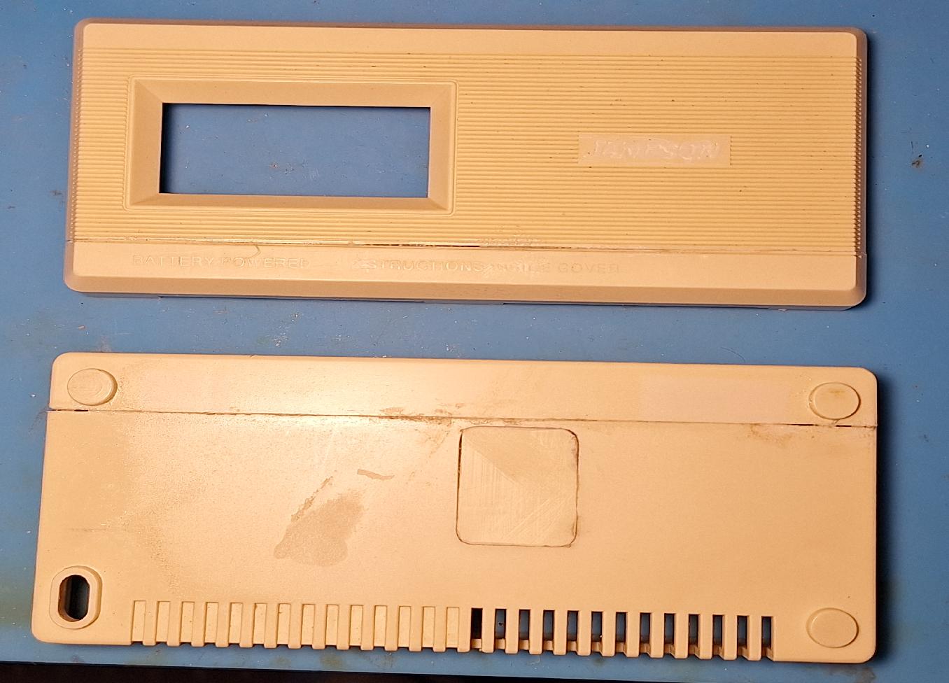
I've filled the hole in the back, and sliced off the old logo with a razor blade. The glue is model airplane cement, which I think is just acetone. Acetone dissolves ABS plastic, so the joints are "welded" together.
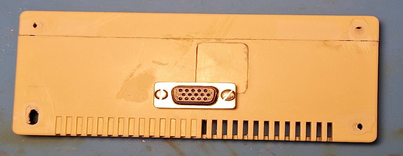
I've cut a hole and "test" mounted the 15 pin connector to the back of the case. I've also sanded off the little "feet" that were on the bottom of the case, as I need it to fit flush to the back of the amplifier.
The TTGO-T-Display doesn't have much in the way of mounting options. There isn't even a hole, but there is a spot where you can make a hole. Other than that, I'll have to clamp the board down with little plastic bits.
Here, I've glued in some of the scrap to locate the board, and also epoxied in a threaded stud (that you can barely make out). I've also drilled the hole for the rotary encoder, but that still needs to threaded holes or studs to hold it in place. Finally, I've used some of the ABS shavings to fill in the holes left by the ground off feet. This was unnecessary but it amuses me to do so.
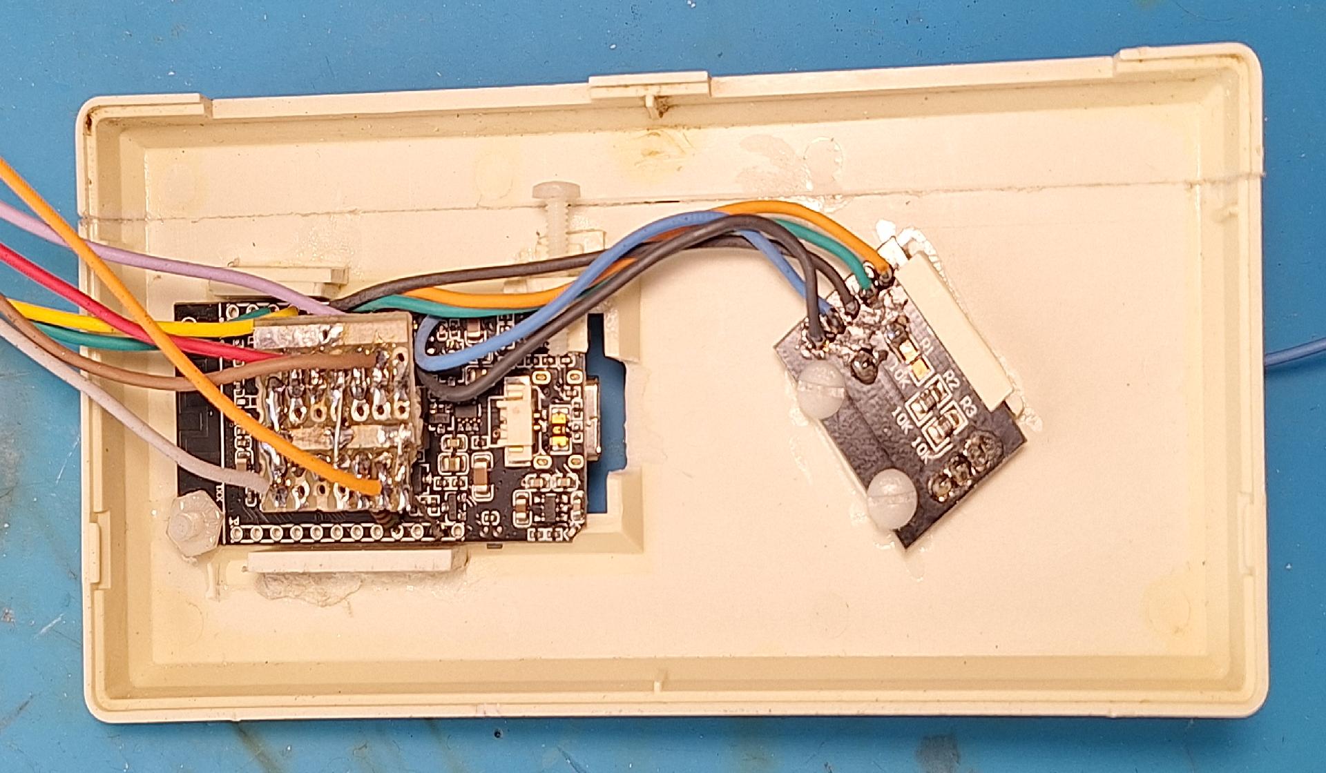
The TTGO-T-Display and rotary encoder are mounted. I may revisit the TTGO board mounting, since it could really use another thing to hold it fast in the lower right corner.
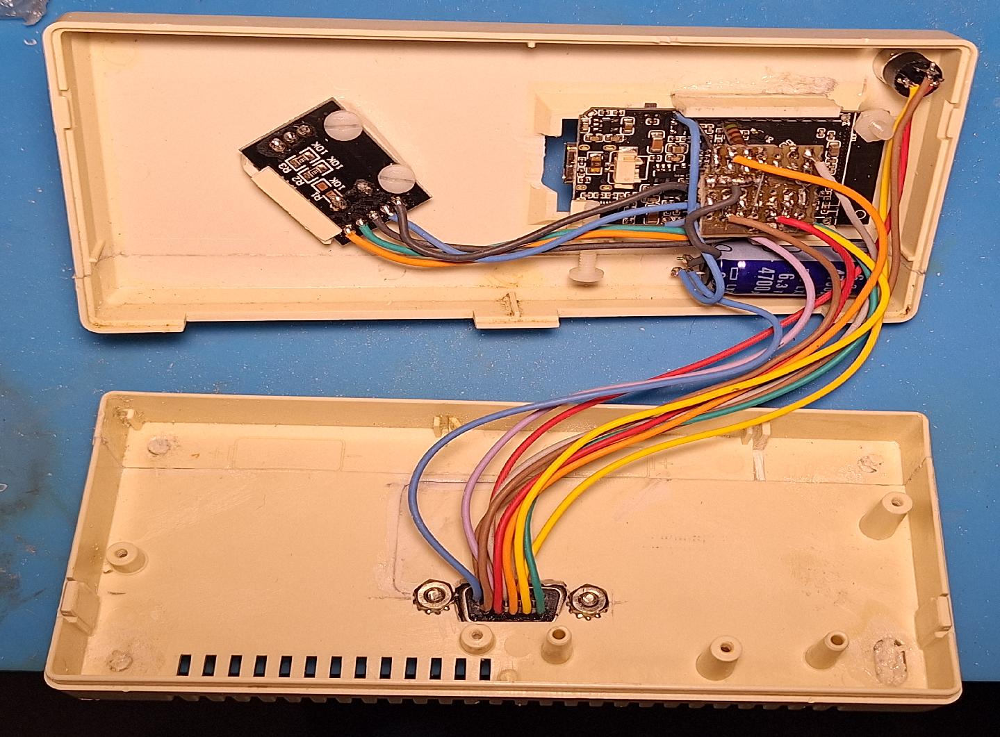
The wiring from the ESP32 (and headphone jack) to the 15 pin connector is finished. You can see the blue 4700 µF capacitor in the lower right just below the TTGO board. I glued it in place using E6000.
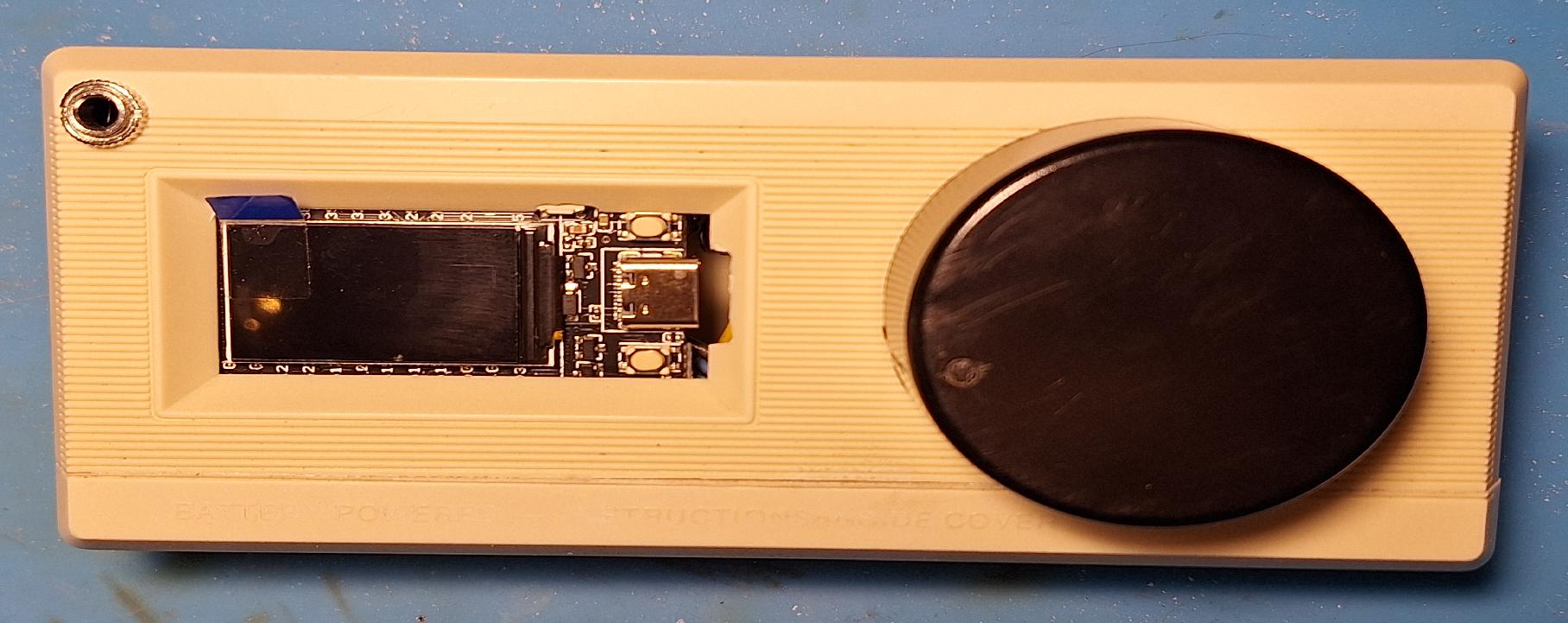
This is it, more or less finished. Is anything ever really finished? The ⅛ jack in the upper left is the headphone jack. I may never use it, but the original product has one.
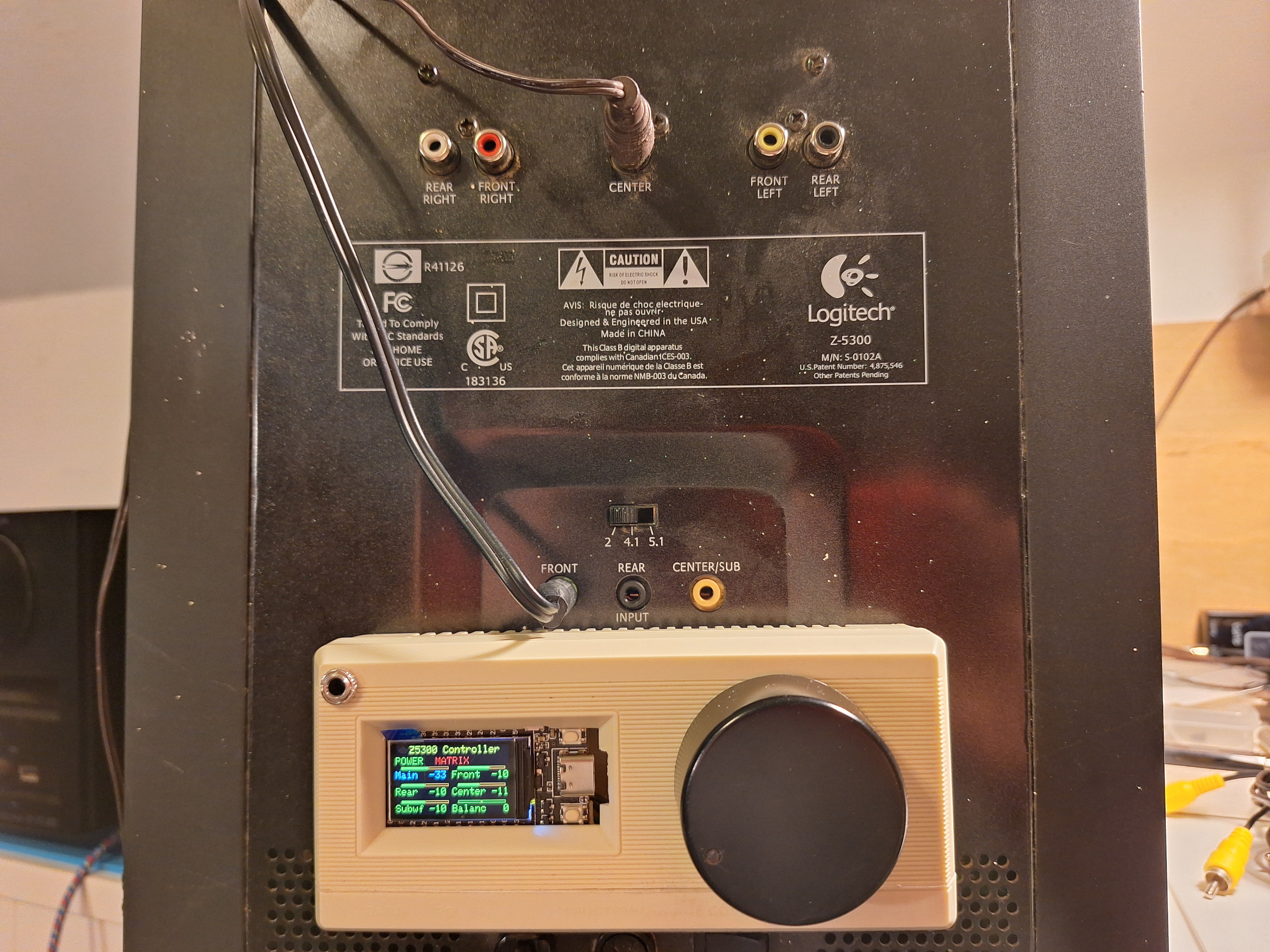
This photo shows the unit mounted to the back of the Z5300 cabinet. Right now, the only thing holding it on is the 15 pin connector. I still want to try to use magnets to improve the "holding".
You can see the "MATRIX" indicator on, which means I have this function enabled. The Matrix function "synthesizes" rear, center, and subwoofer channels from the front channel inputs. I'm feeding in a stereo signal into the "FRONT" jack, and getting mono Subwoofer and mono Center channel from it.
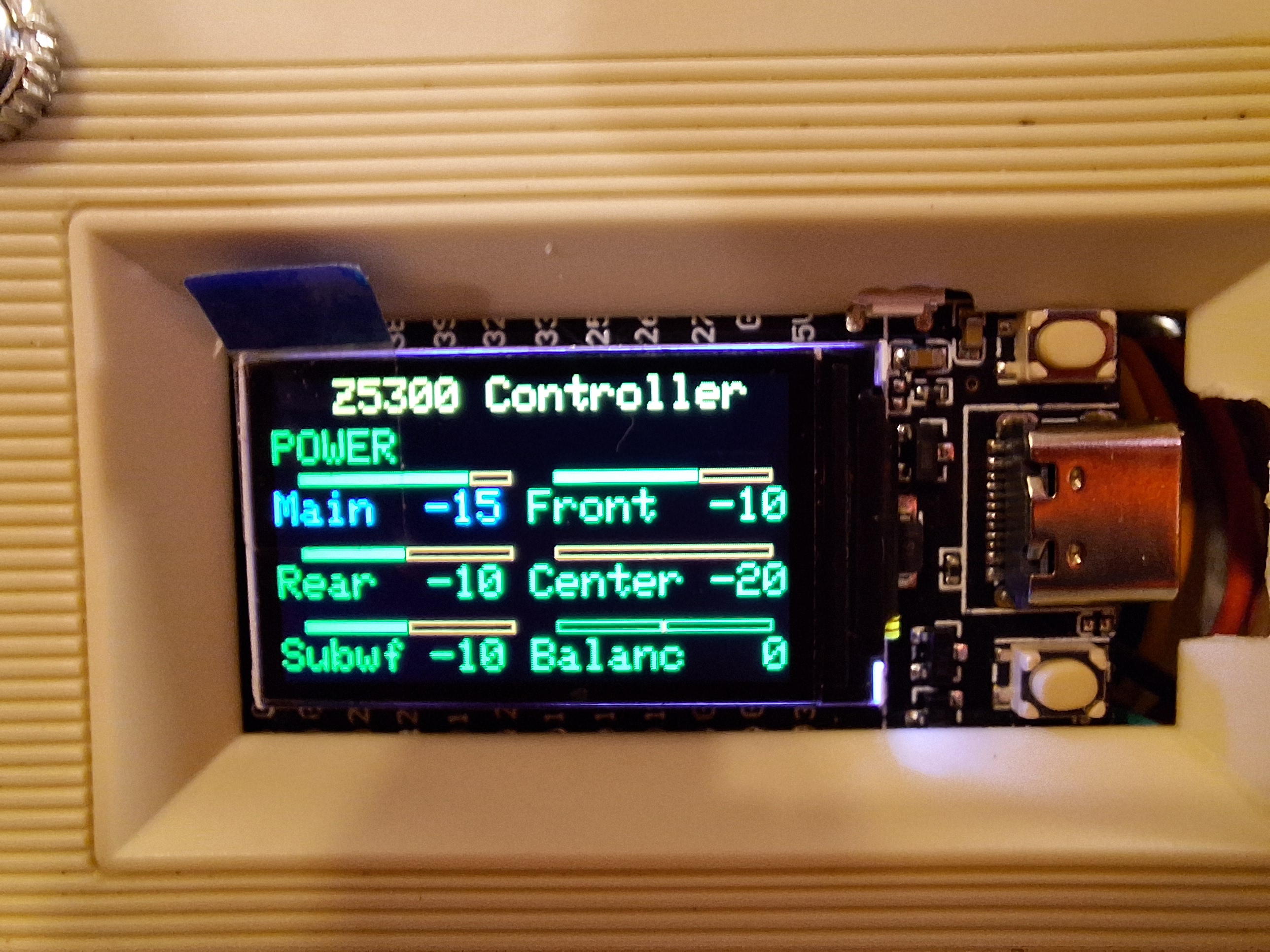
Close-up of the display. Eventually, I may glue on some plastic to cover up the right side of the PCB.
I've added two screws that come in from the back and thread into "bosses" (made of more plastic scraps) to hold the halves together. The plastic clips (of which only 2 survived the major surgery) weren't strong enough to reliable hold front to back.
I also put two small magnets in the back, to help hold the box to the steel amplifier chassis. Finally, I built up two bosses that meet in the middle so that when you push on the front of the box, the back of the box carries the force into the 15 pin connector. This is to help seat the connector without the back of the box bowing under pressure.
William Dudley
May 12, 2025


 Views
Views