Talkie Toaster from Red Dwarf™
Note: Click on the pictures to embiggen.I've been collecting "robots" for a while now, and realized I didn't have "Talkie Toaster" from the TV series Red Dwarf in my collection. I decided to make one; it should talk, but not be capable of toasting bread.
First, I needed a toaster. I found a toy (available via Ebay and Amazon) that is from England (but made in China): a toaster and a kettle, that are about 1/2 scale. The toaster has a chrome plated plastic body and is more or less "normal" looking, i.e. it isn't pink or something else weird.
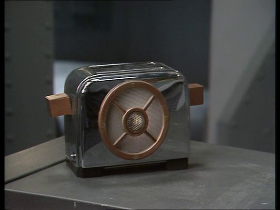
The toaster from the TV show, season 1, episode 4, "Waiting for God".
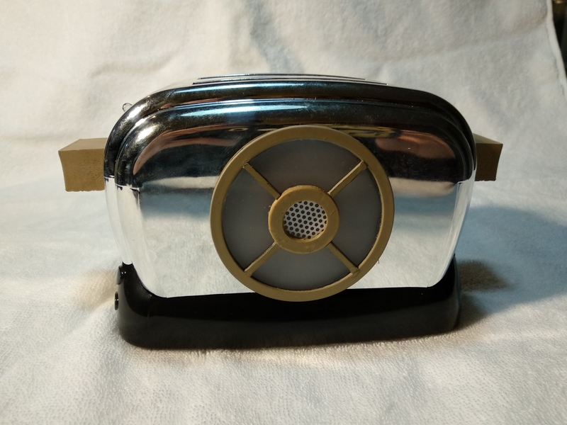
My replica.
I already know how to make "toys that talk". Just buy a "DFPlayer Mini" from the usual sources (Ebay, Amazon), load up your micro-SD card with clips from the movie/tv show, and wire the DFPlayer to battery, speaker, and push button. As Hollie would say: "Easy-peasy".
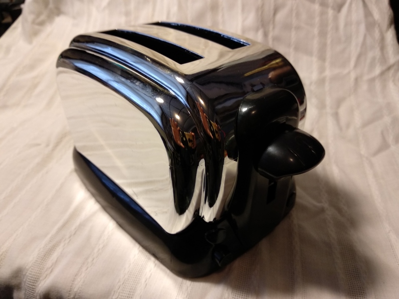
Toy toaster as it comes out of the box.
First step: disassemble the toy, remove the clockwork bit that ejects toy toast slices, the ugly knob and escutcheon plate behind the knob. Also, the knob on the other end that controls the clockwork.
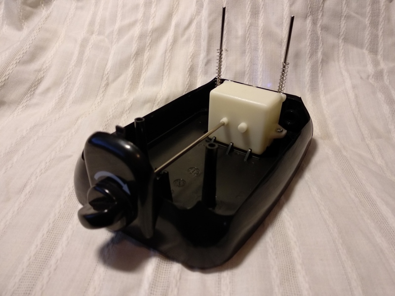
Inside the toaster showing clockwork box and associated knob. This all comes out. The vertical metal rods and springs stay.
I cut the "push to lower toast" knob off of the rest of the "toast platform", cut a hole in that part, and glued the speaker to it. The "toast platform" will remain stationary, but the "push to lower toast" button will still function (to make the sounds play).
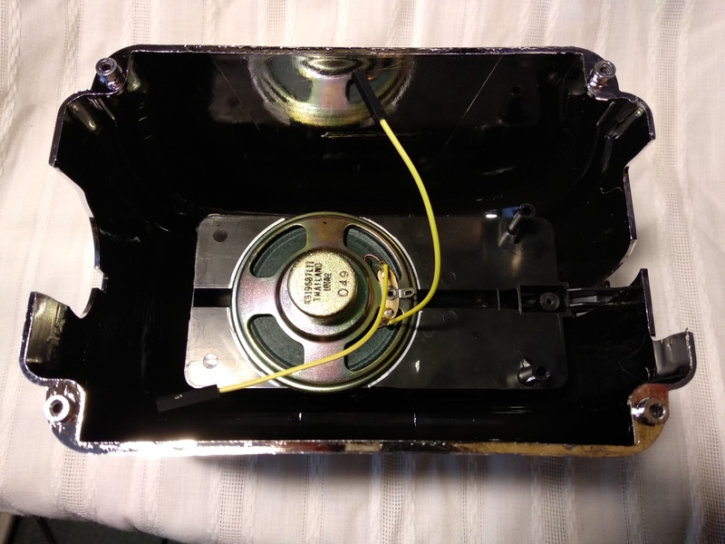
Speaker glued to underside of "toast platform". Later I would cut off the bit on the right that slides on the vertical steel posts, and also unglue and re-glue the speaker in a slightly different spot. In case it isn't obvious, I'm building this without any kind of "master plan". I'm winging it.
With the clockwork bit removed, there's lots of room in the base for a battery. Use any Lithium battery you like, but you will need a power switch, as the DFPlayer mini idles at 16mA. I used an old 18650 from a laptop battery pack. I wired it to a 350mA fuse (from my junk box) to a generic Lithium battery charger. The battery charger has terminals for both load and battery, so I don't have to disconnect from the load to charge (though, with a power switch, this is moot.)
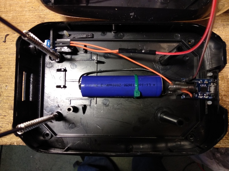
Battery and charger mounted in the base of the toaster. Power switch is hard to see on the upper left. Springs are glued in at one end, so that they are less annoying when assembling the toaster.
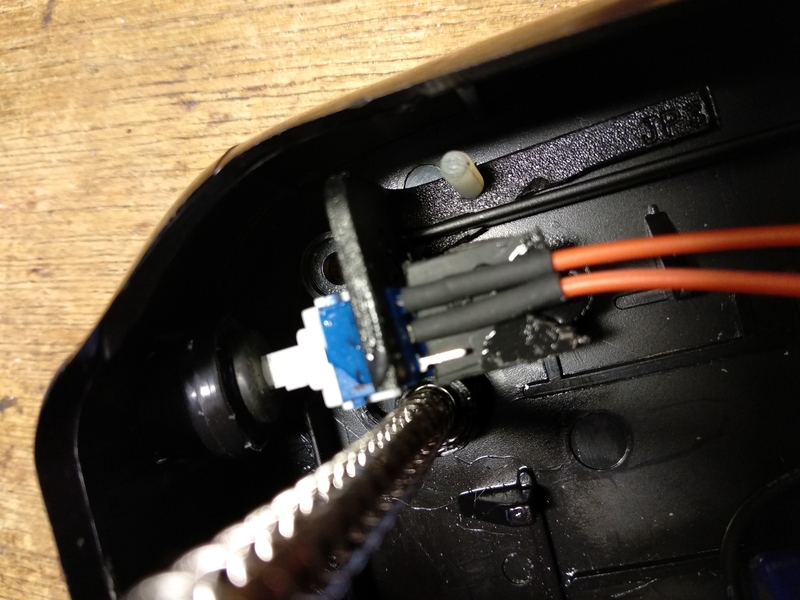
Close-up of power switch. That's a rubber grommet pushed on to the end of the button, and that in turn is glued into the fake "darkness" knob from the toy. I reamed out the hole in the toaster "base" a bit so the knob moves in and out easily. The result is that the brightness knob is now the power push button (push on, push off).
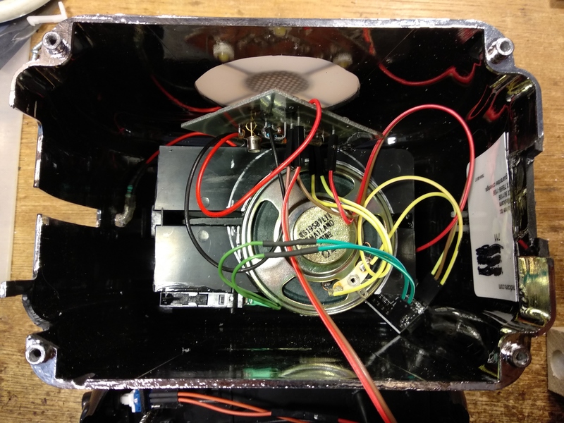
The mostly finished toaster. I've cut a hole in the side, and glued on the translucent window and grille. I've taken that "waste" piece of plastic, and cut and filed it until it fits in the hole where the clockwork knob and escutcheon plate were (on the right side in the picture). That bit of white plastic is an old credit card used as backing where I glued in the patch. From the outside, it isn't very noticable.
You can also see that I've moved the speaker, because it was interfering with my LED driver circuit board (discussed later). Also visible, just lower left of the speaker, is a microswitch, that will be actuated by the "push to lower toast" knob. Finally, there's the back of a blinky red LED (and 1K resistor) that are glued into the case on the left side; it flashes when the power is on to remind the user to turn it off when done playing the sounds.
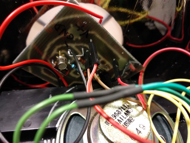
That's the "best" view of the circuit board that I've got, but it's an ugly hack, so that's OK. I've got so much stuff glued in that I can't easily remove the circuit board to photograph it properly. The board just amplifies the audio and drives four LEDs behind the translucent grille. (Schematic below).
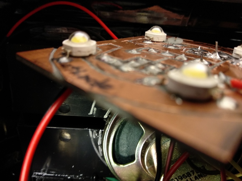
Crappy photo of the copper side of the board. I cut this out using a Dremel, by hand. "Crude but effective".
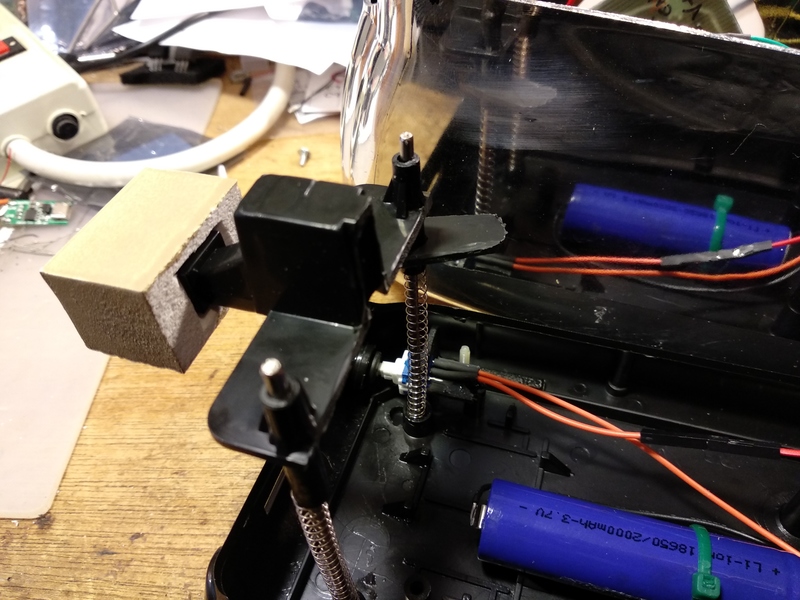
The "toast lowering" lever, now is the "talk" button. Original knob replaced by a block made of a scrap piece of vinyl trim (1x4 or something). That stuff is easy to "machine" so easy to make a square hole for the "shaft" of the actuator. That little "ear" that sticks out to the right is a bit of scrap plastic that's glued on, and which pushes on the microswitch when the lever is all the way up.
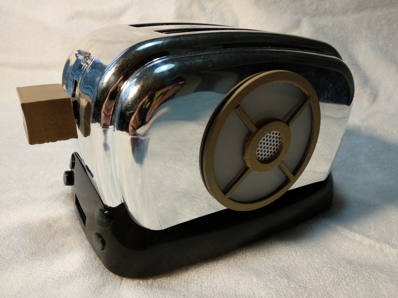
Another view of the "finished" toaster.
See it in action!
Circuit Description
The DFPlayer Mini drives a speaker directly, with outputs that have DC level of Vbattery/2, or about 2V assuming a nearly fully charged Lithium battery at 4V. You will want a momentary push button across the "Next" and "Ground" pins, to tell the unit to play the next "track". The DFPlayer Mini runs on 3.5 to 5V, so a single Lithium cell is perfect.
To get LEDs that flash with the sound (as this and other toys do), I have in the past just hooked some LEDs back to back across the speaker leads. This works "OK"-ish, assuming you don't want much light.
For Talkie Toaster, I needed to light up four decent sized LEDs enough that they'd show through the translucent grill, in the daytime. (Not necessarily in bright sunlight. I'm not taking this to the beach.) To get enough brightness, I made a simple amplifier using a single NPN transistor (a 2N2222, but pretty much anything would work here).
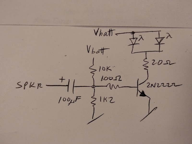
The 10K and 1K2 (1.2K) resistors make a voltage divider that biases the base of the transistor up to .4v or so. This means that the audio coming through the capacitor only has to have amplitude over about .6v peak to peak to start turning on the transistor (and hence the LEDs). Without this bias, the amplitude to begin lighting the leds is more like 1.4v, so then the LEDs aren't as sensitive. The 100uF cap can be smaller; 10uF or even 1uF work OK. It's not like we're trying to pass low bass or anything. Talkie's voice is kinda high pitched.
The 20ohm resistor is an arbitrarily chosen value to limit the max current through the LEDs and the transistor. I didn't make any calculations, I just stuck it in there because it felt "right". All resistors are 1/4 Watt 5%. Values are non-critical, except that the voltage divider should have about the same ratio as my divider.
FAQ
Q. Will you make one for me?
A. No, I'm retired and so not interested in a job.
Disclaimer/Warning
This is just my "build log". I don't claim that building this is safe or recommended.
Be careful when handling Lithium batteries, they can explode or cause a serious fire. Don't short them out and don't physically abuse them.
Soldering irons are dangerous, be careful. Oh, and don't eat the solder.
Track Back
William Dudley
January 18, 2020
revised February 13, 2020


 Views
Views