Repairing a Pocket-PC with a bad Li-ion charger, or building a USB powered Li-ion charger. |
|
I have a T-Mobile Pocket-PC (actually OEM HTC PW10B1 ), and the internal charger for the Li-ion battery pack stopped working. Since the internal battery pack is comprised of a single Lithium ion cell the charger needs to charge the pack to 4.2V. This website shows how to build a charger to charge a single 4.2V cell from a 12V supply. Since the Pocket-PC is charged from a USB connection, it needs a low drop out regulator, so the above cited solution won't work. As an experiment, I threw together this low drop out charger using discrete transistors. It works, but the charge current isn't quite as high as I'd like, and it's got too many parts to fit in the Pocket-PC.
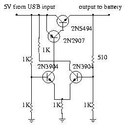
My discrete charger consists of a compound transistor (a pnp driving
an npn pass transistor) which is driven by a differential amplifier (the
pair of npn transistors sharing the same emitter resistor). The diff
amp compares the reference voltage (the two 1K resistor divider voltage,
about 2.5V) with a sample of the output voltage (the 510/1K divider)
and drives the compound transistor to attempt to maintain 4.2V at the
battery terminal.
My cousin, who has more analog design experience in his fingernail clippings than most engineers ever know, recommended I go check out Maxim for a battery charger IC. A search of the Maxim web site found many battery chargers: NiMH, NiCd, Li-ion, generic, single-cell, multi-cell, etc., and I selected the MAX1811 USB powered Li+ charger because:
This is the suggested application circuit: the bypass cap on the 5V input is a 4.7μF, that on the output is a 2.2μF. Tying SELV, SELI, and EN to IN configures the MAX1811 so it will charge to 4.2V at a maximum current of 500mA.
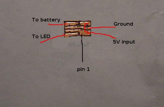
I carved out a 1cm square circuit board (using my Dremel) to hold the
'881. Here is a picture with crude annotations showing the connections.
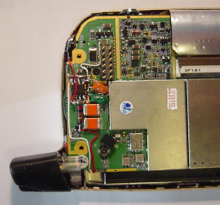
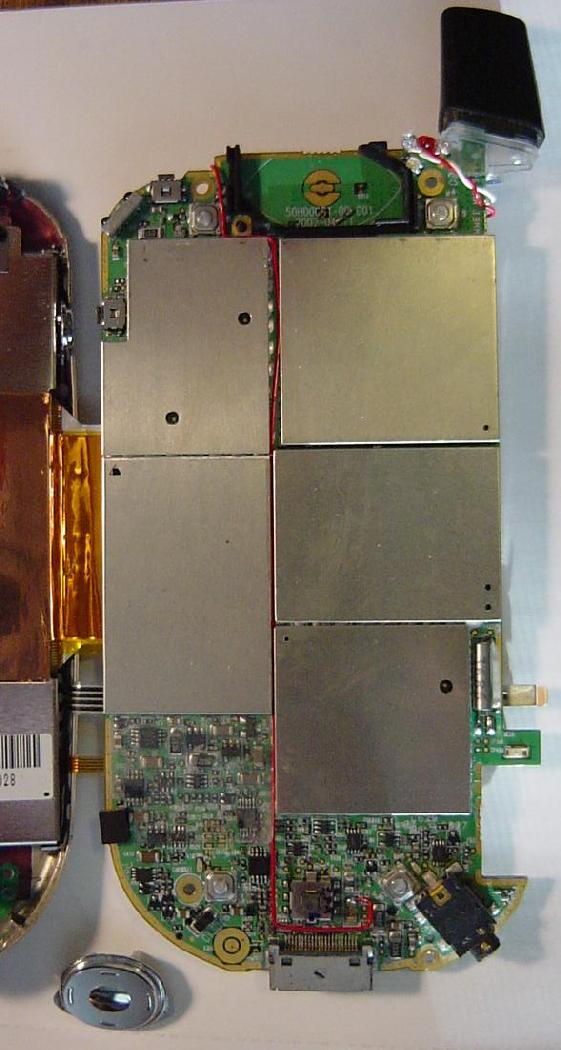
A small blob of Goop holds it and the two capacitors down to a blank spot on the Pocket-PC circuit board. 30 gauge kynar™ covered wire-wrap wire connects the 5V from the USB connector to the input, and the 4.2V (nominal) output to the battery pack. In addition, I wired a tiny red LED to the /CHG pin on the '881, and fit (jammed) it next to the internal green/yellow LED and the plastic light-guide in the Pocket-PC. When the charger is active, you can just make out a red glimmer mixed in with the yellow light from the internal LED. This first photo shows the regulator circuitry in place on the main board. The red wire coming over the top (in the photo) of the board is the 5V feed. The white wire at the top of the photo runs from the output of the MAX1811 to the left side of the fuse that then feeds the charge current to the battery pack.
The red and white wires that go off the bottom edge of the main board
go to the red LED. This LED, the 200 Ω resistor that limits its
current, and the wires to it, are of course entirely optional. You can
just see a bit of the red LED peeking out from under the circuit board
on the left side just above the dummy plastic antenna thing.
The second photo shows the wire that carries 5V from the USB input
connector (at the bottom of the photo) to the input of the regulator,
and also shows the charge LED placed near the stock green/yellow LED
(at the top right of the photo). The feed point for the 5V is the top
of the (surface mount) fuse. I have removed the chromed plastic
"joy-button" thingy from it's switch mechanism so that you can see
the fuse, which is normally hidden under the button.
It works! A $200 Pocket-PC saved from the landfill.
Bill Dudley |
    Views Views
|