Repair/upgrade of Onkyo HT-RC430 AV Receiver - Hardware Details
| Name in the source code | ESP32 or MCP23017 pin | other end | comment |
|---|---|---|---|
| HSPI_MISO | 12 | n.a. | not used, display is write-only |
| HSPI_MOSI | 13 | P701 22 | M66005 display controller MOSI |
| HSPI_SCLK | 14 | P701 23 | M66005 display controller SCLK |
| HSPI_CS | 15 | P701 21 | M66005 display controller chip select |
| SPRLSPB | GPA7 | P8002 1 | 'B' and surround speaker relay |
| SEC1H | GPA6 | P8002 2 | more power control |
| AMUTE | GPA5 | 2 transistor mute driver circuit | mute all audio |
| SEC1OFF | GPA4 | P8002 4 | more power control |
| SPRLF | GPA3 | P8002 6 | front speaker relay |
| MPOWER | GPA2 | transistor driving JL901 1 | main power |
| BTPOWER | GPA1 | base of 2N2907 to power BT module | bluetooth power |
| LEDSTBY | GPA0 | LED | front panel LED |
| REPEAT | GPB0 | transistor base to drive "repeat" button | bluetooth board repeat button |
| PREVVDN | GPB1 | transistor base to drive "previous" button | bluetooth board previous track button |
| NEXTVUP | GPB2 | transistor base to drive "next" button | bluetooth board next track button |
| PLAYPAUSE | GPB3 | transistor base to drive "play/pause" button | bluetooth board play/pause button |
| BTMODE | GPB4 | transistor base to drive "mode" button | bluetooth board mode button |
| KEYPIN0 | 39 | P701 2 | analog input for key scan group 1 |
| KEYPIN1 | 36 | P701 3 | analog input for key scan group 2 |
| KEYPIN2 | 34 | P701 13 | analog input for key scan group 3 |
| KEYPIN3 | 35 | P701 15 | analog input for key scan group 4 |
| POTA | 4 | P701 12 | digipot A |
| POTB | 5 | P701 14 | digipot B |
| DISP_RES | 16 | P701 19 | display reset |
| VOLDATA | 19 | P8002 5 | data line to audiofp device (R2A15218FP) |
| VOLCLK | 23 | P8002 7 | clock line to audiofp device |
| SPRLCS | 2 | P8002 8 | center/surround speaker relay |
| TUNER_RES | 18 | P8001 2 | Tuner Reset |
| ESP32_I2C_SDA | 21 | P8001 4 & MCP23017 SDA | I2C TUNER & MCP23017 |
| ESP32_I2C_SCL | 22 | P8001 6 & MCP23017 SCL | I2C TUNER & MCP23017 |
| HS_TEMP | 33 | JL501 3 | heat sink temperature from LM61 - V = 0.6 + tC/100 |
| HP_DETECT | 17 | P8001 18 | head phone detect - low when not plugged in |
| I2S_BCLK | 25 | I2S module BCLK | I2S DAC for Internet Radio |
| I2S_DOUT | 26 | I2S module DOUT | I2S DAC for Internet Radio |
| I2S_LRC | 27 | I2S module LRC | I2S DAC for Internet Radio |
| unused | 32 | n.a. | analog/digital |
| unused | GPB5 | n.a. | digital |
| unused | GPB6 | n.a. | digital |
| unused | GPB7 | n.a. | digital |
Other Hardware
I added a small switching supply from the power cord input (i.e. unswitched) that supplies 9V to the ESP32 board via a 7805 regulator. (The ESP32 has a regulator of it's own to make 3.3V). The ESP32 is always running as long as the line cord is plugged into mains electricity.
The "power" LED is one glued into a hole I drilled in the "O" in "Onkyo", because I coudn't find a power LED on the front panel PCB. It is driven by the output called "LEDSTBY". It flashes during boot up; 1 time, 2 times, 3 times, 4 times, and 5 times once it is fully up and has a WiFi connection. The ESP32 only boots up when power is applied; the "ON/Standby" just tells the ESP32 to turn off most of the power in the unit, save the ESP32 itself.
The speaker connectors have had Banana jacks wired up in parallel with the A and B speaker outputs, because the stock speaker connectors suck.
William Dudley
April 19, 2025
More photos
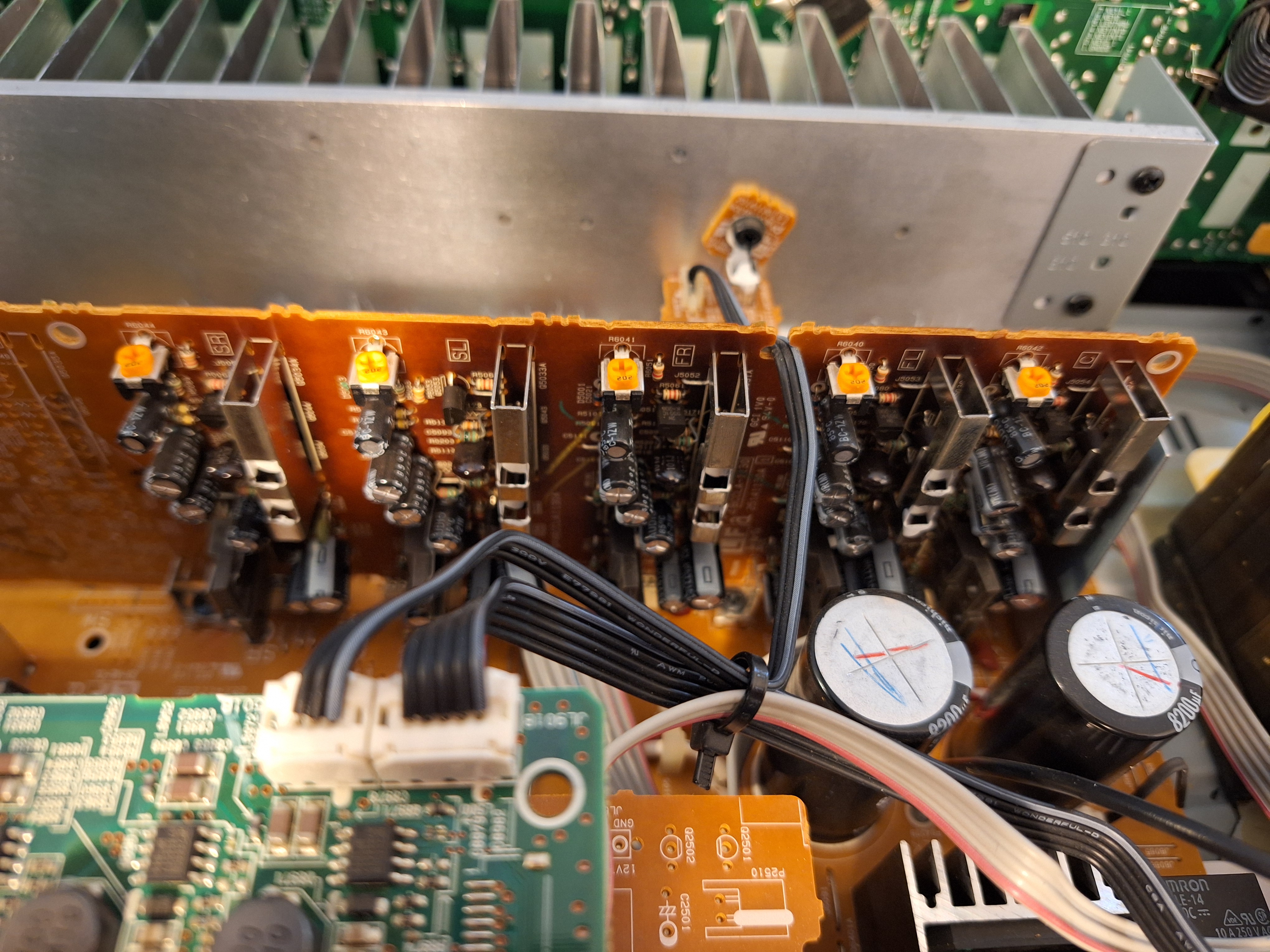
The amplifier driver board, which claims to be class A. It sure throws off some heat when listening at moderate levels. At top of photo you can see the temperature sensor (an LM61) attached to the heat sink.
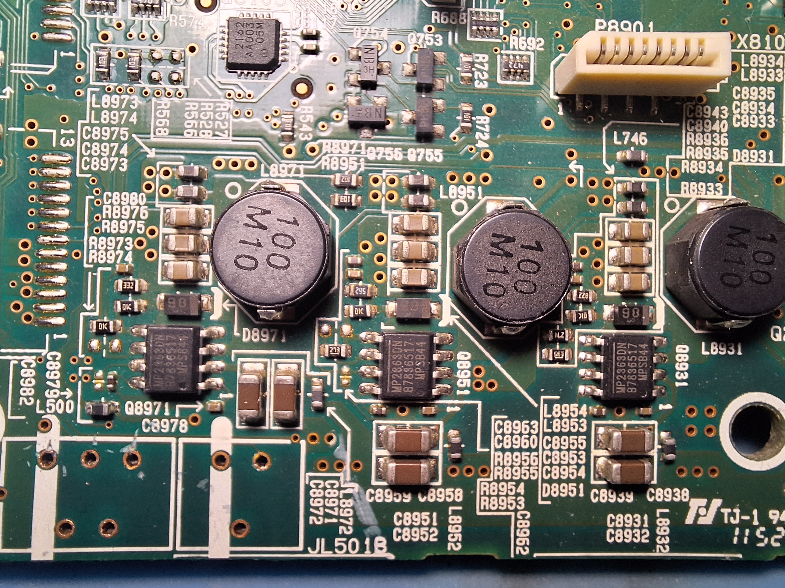
Detail of part of the stock CPU board, showing the places where a wiring harness was soldered in, that I connectorized.
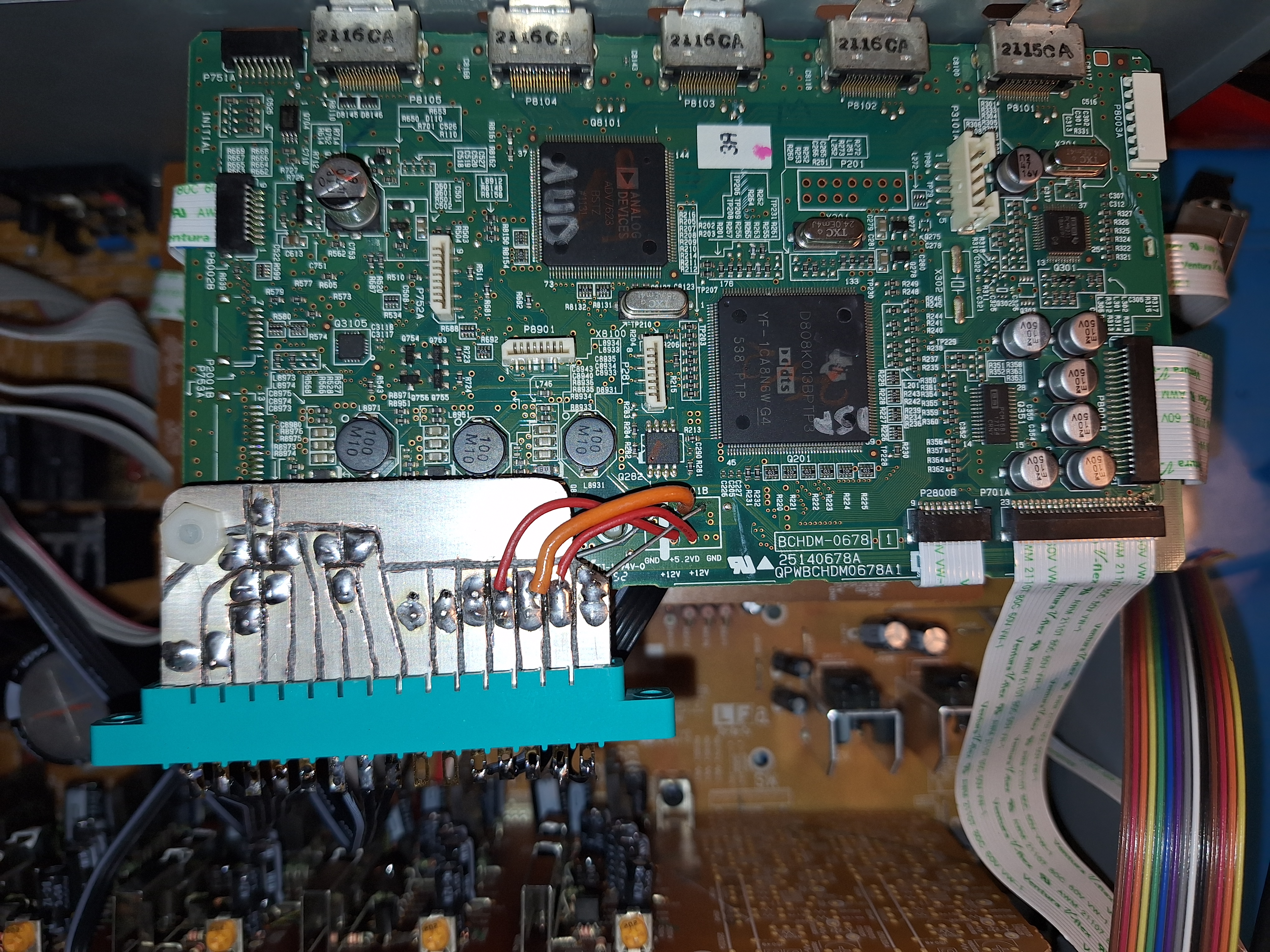
The stock CPU board after I connectorized the soldered connections, so I could remove/replace it at will.
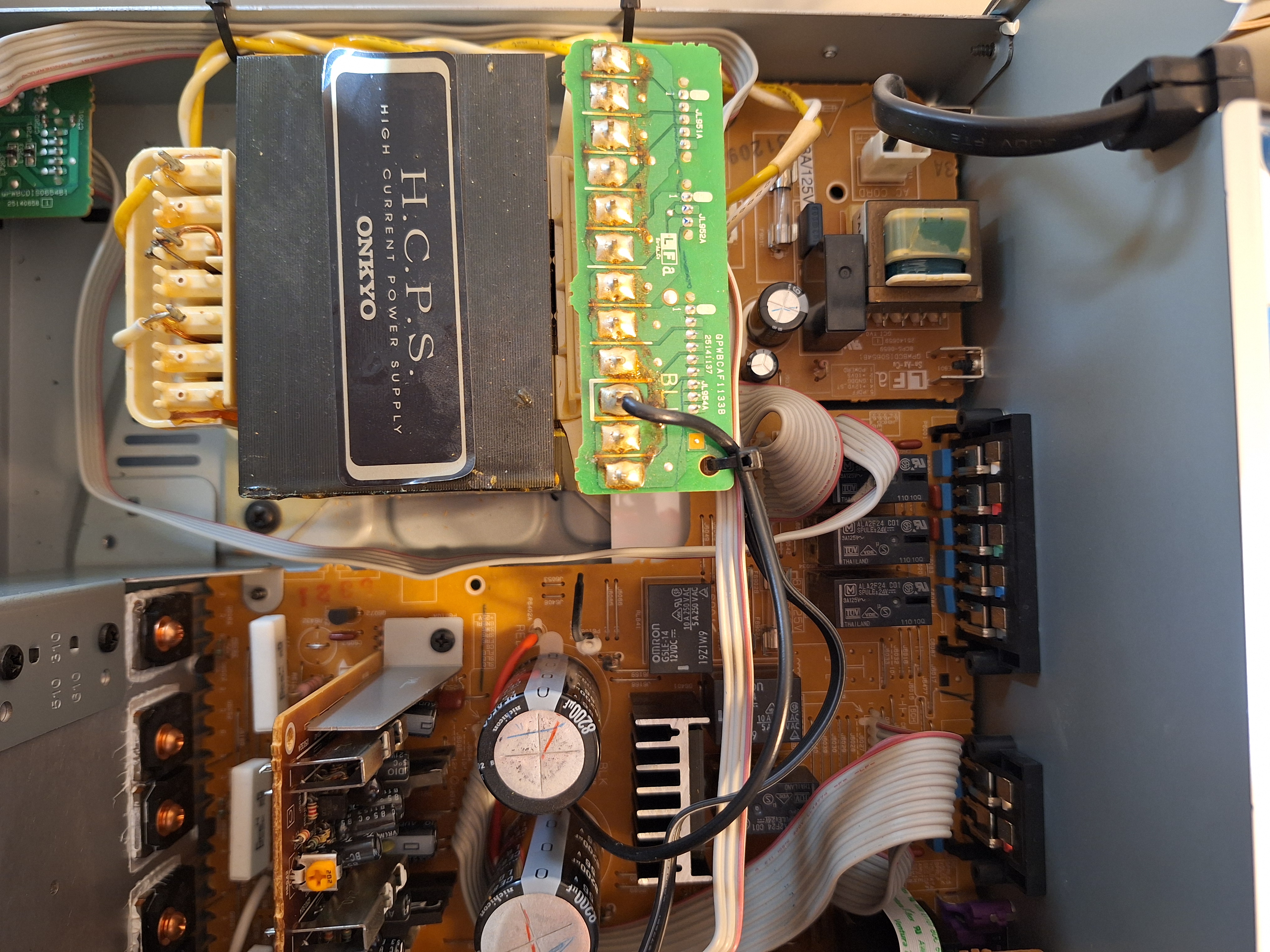
The power supply section (and part of the amplifer at bottom). A good part of the power supply circuitry is on the video I/O board, which you cannot see.
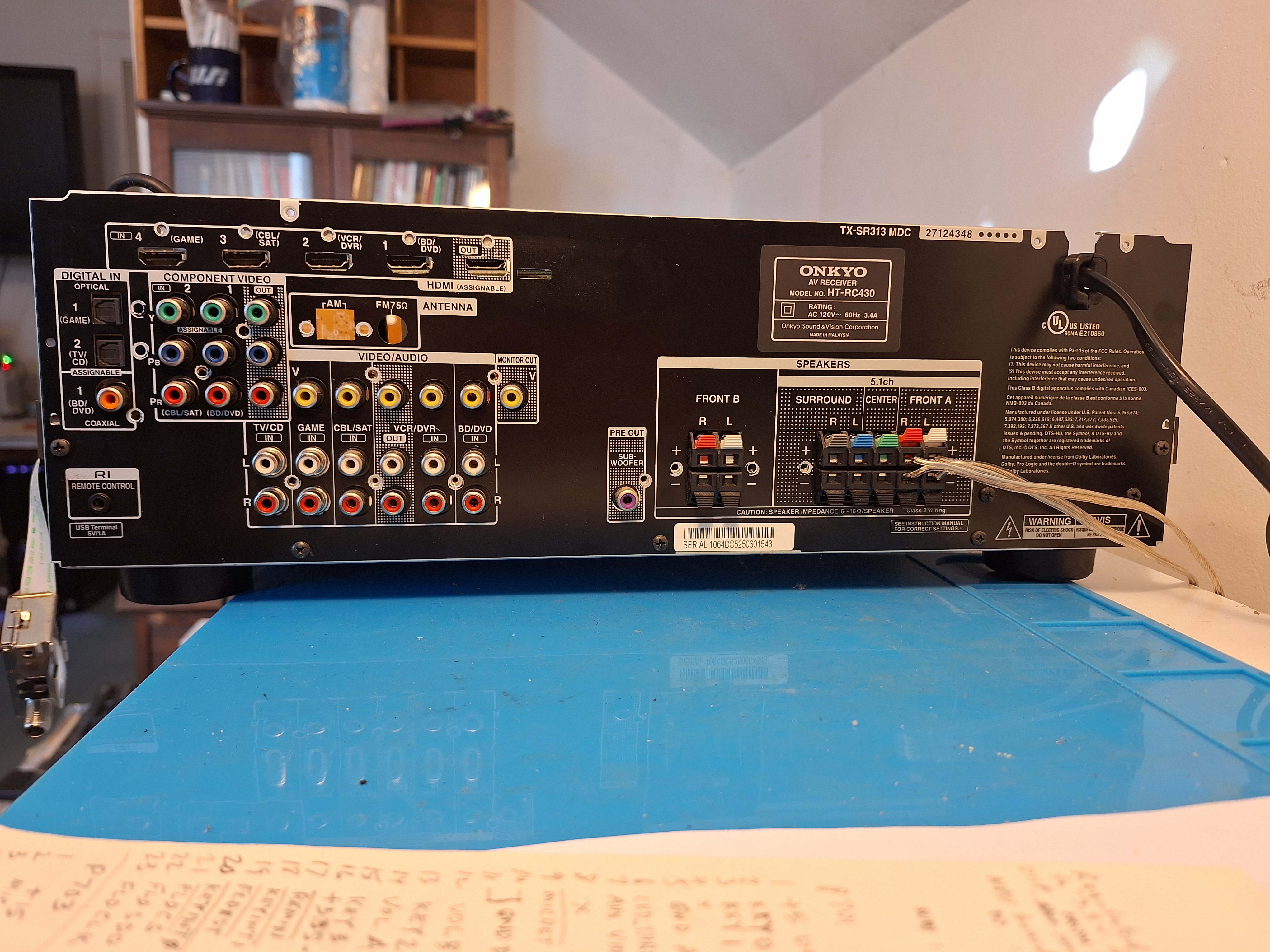
Rear view of the unit with the tuner removed, hence the two holes labeled "AM" and "FM 75Ω".
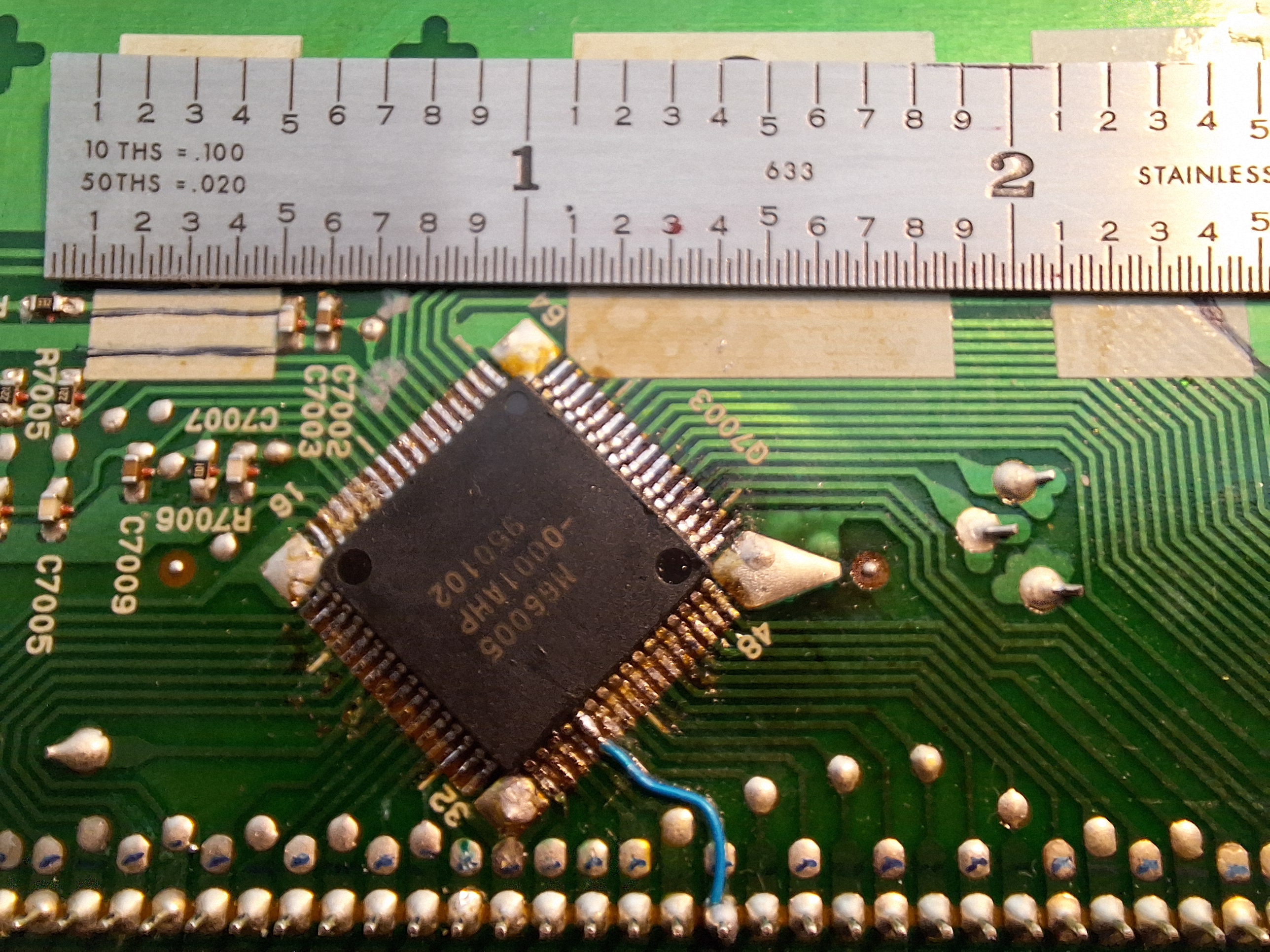
Close up of the VFD driver chip after I replaced it, showing bodge wire because I destroyed a track in the process.


 Views
Views