Automatic Fan Switch for Power Supply
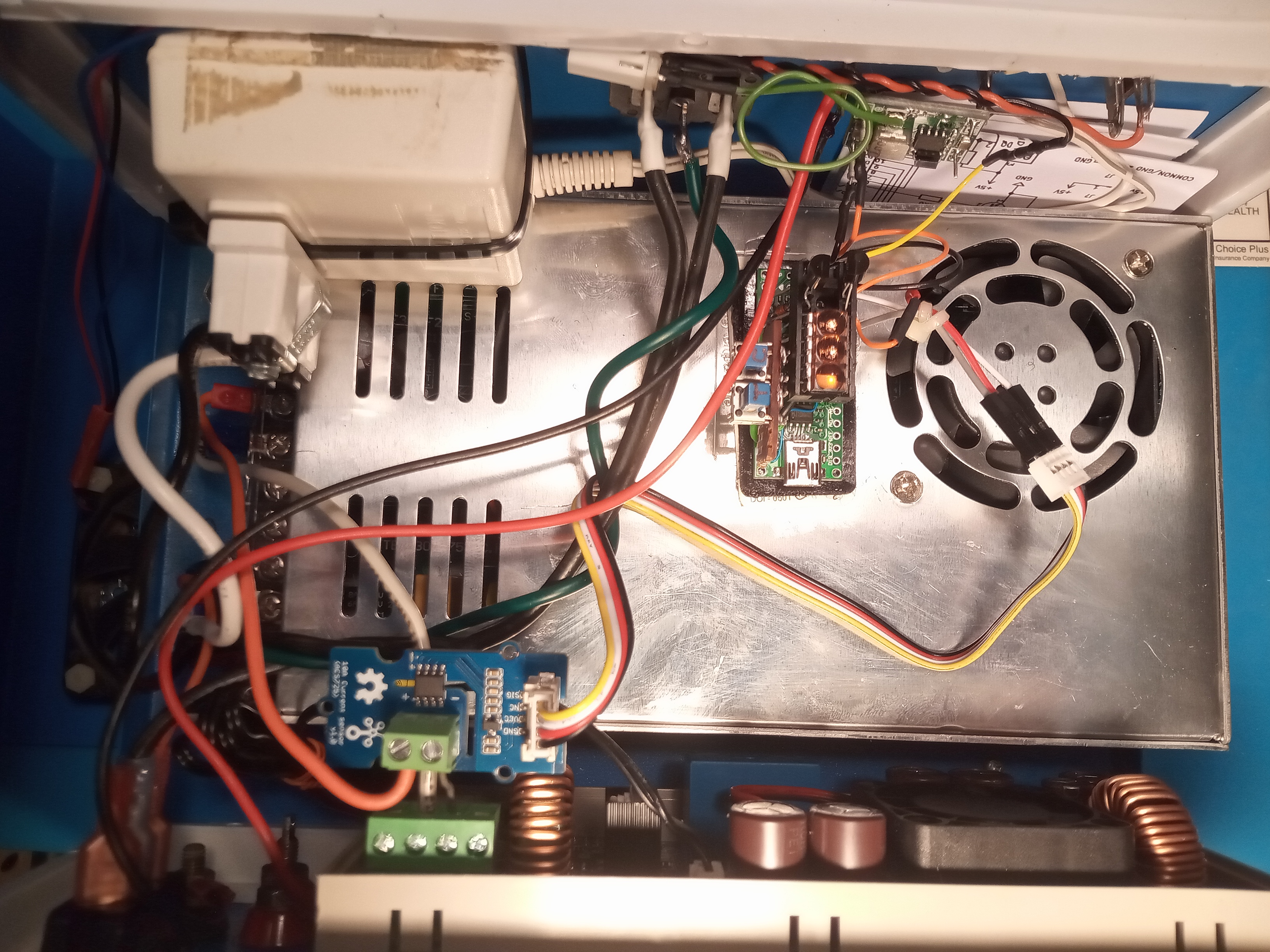
Top view of the finished fan switch inside the power supply.
In an earlier episode, I built a bench power supply using one of those universal power supply modules made by Riden. After some fooling around with a power source consisting of a transformer, diodes, and a cap, I ended up buying a 60V 6A switching power supply to act as the unregulated input to the Riden. During this "development", I decided that a fan inside the box was a good idea. I slapped in a small computer fan.
The fan worked to keep the temperatures down, but the noise from the fan was annoying. It occurred to me that the fan didn't need to run when the power output from the supply was "minimal" (yet to be defined at this point). The answer was to make a device that only ran the fan when the current output was non-trivial. I later decided that I could also switch the fan based on the temperature in the box.
The "old school" way to add fan cooling would be to use a mechanical thermostat to switch the fan on and off. That's silly in 2021. An Arduino UNO can easily handle this job, and with much more flexibility.
The hardware I chose (ended up with?):
- Arduino Nano V3 -- this is the version with an Atmega 168, which at 16K of code space, still has plenty of room for such a trivial program.
- Two character 7 segment display -- I had some "antique" HP "bubble" displays in my junk box, so I'm using a 5082-7432 dual bubble common cathode display.
- Temperature measurement is handled by a Dallas DS18B20. Super accuracy isn't called for here.
- 2N2222 transistor is used to switch the fan current, as the Arduino outputs can't switch 12V, nor handle the fan current.
- ACS712 module to convert current to voltage. The version I used can measure up to 10A DC.
- Two pushbuttons for the user interface.
- 8 470 ohm resistors for the LED display, a 4.7K for the DS18B20, and a 1K for the base of the 2N2222.
- Almost any diode to handle any back-EMF from the fan. I used a 1N4148. A 1N4001 might be a better choice.
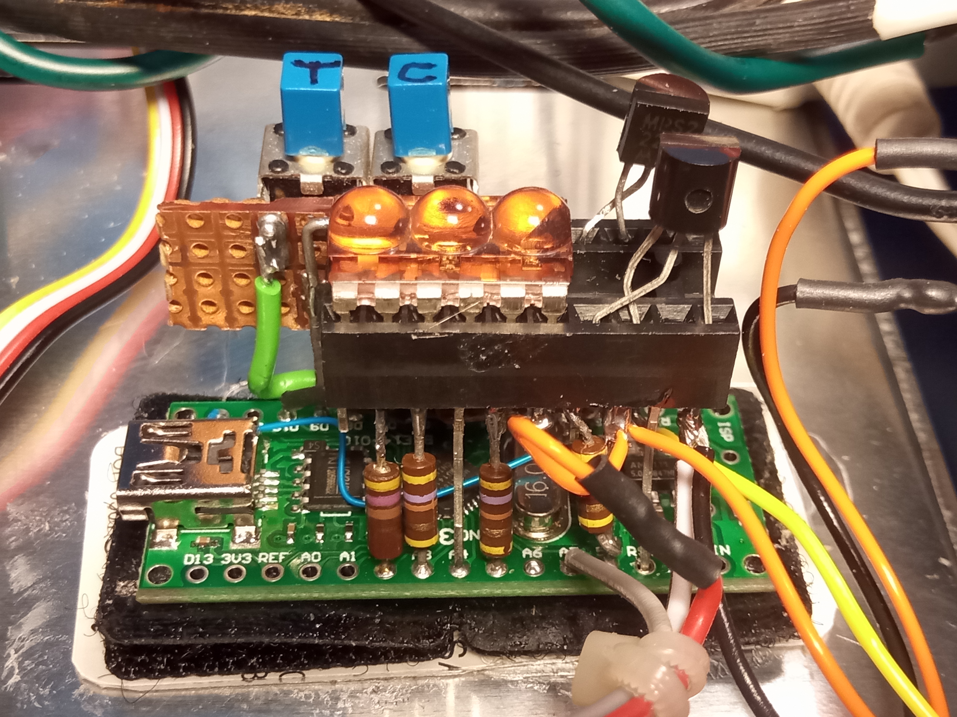
Close up of the finished fan switch.
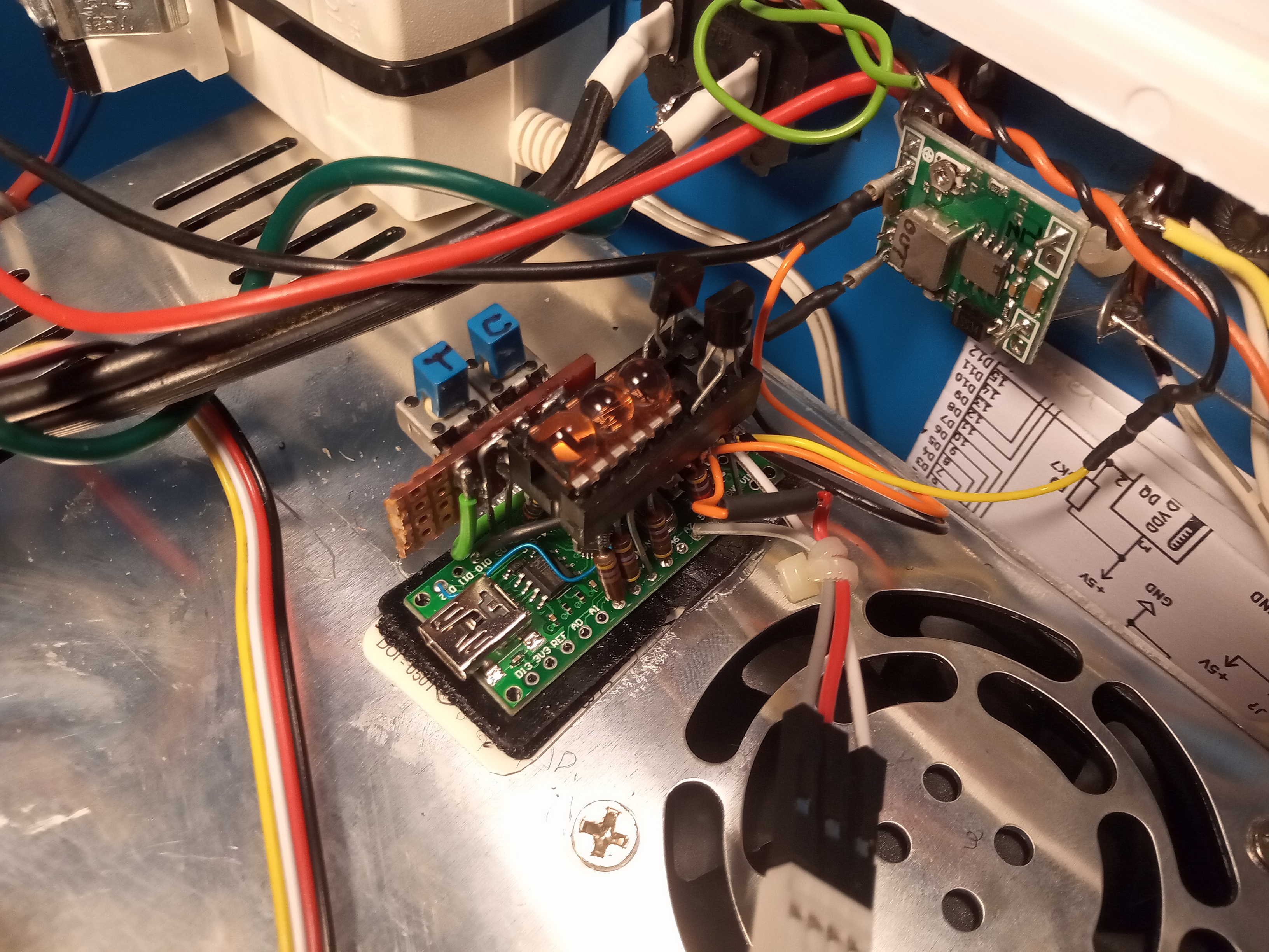
Another view showing connection to the 5V (switching) regulator (upper right).
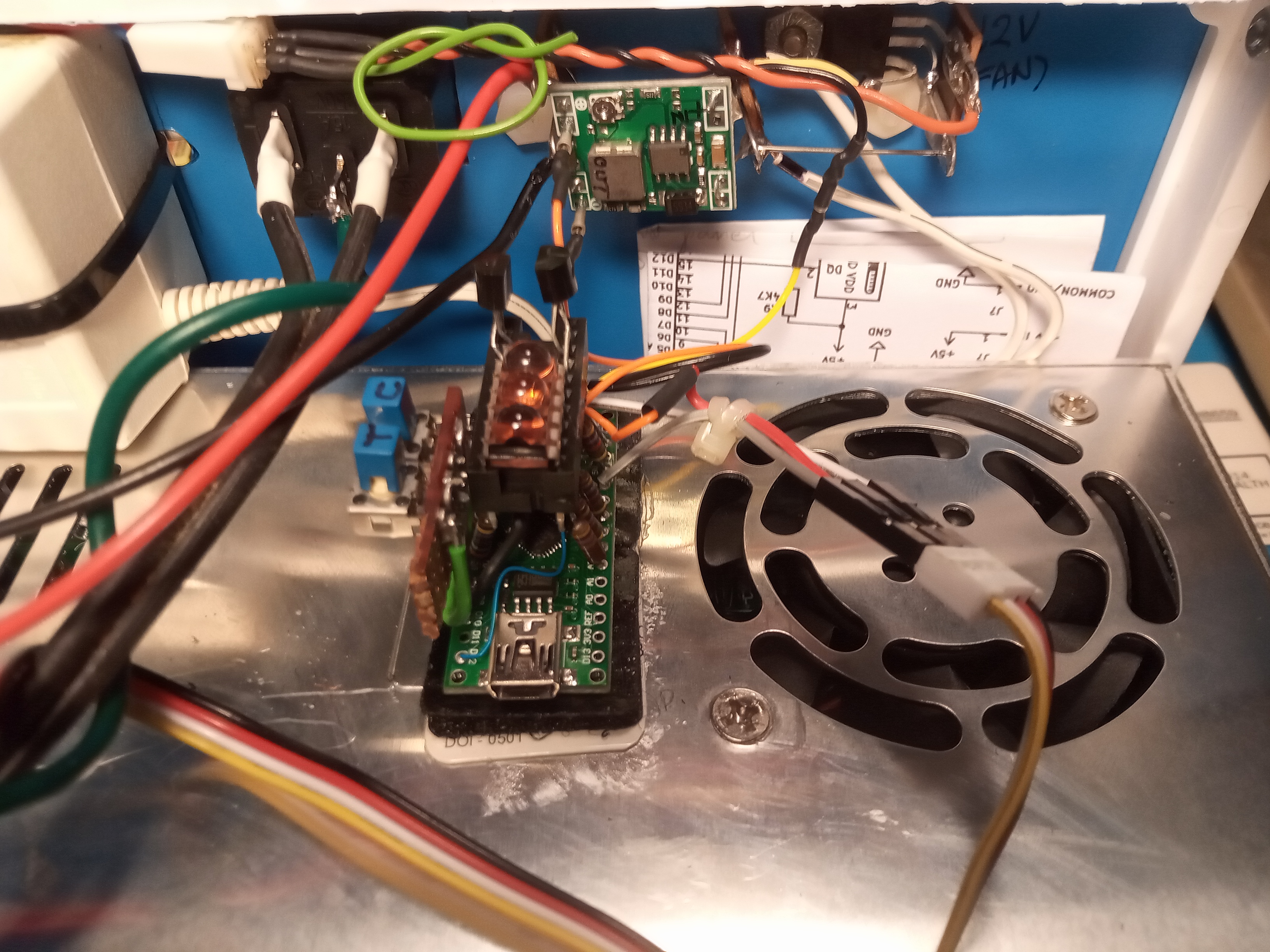
Yet another view showing push buttons on a scrap of perf board hanging off the left side of the Nano.
Features
- Upper and lower current thresholds, so there is hysteresis in the fan decision.
- Upper and lower temperature thresholds, so there is hysteresis in the fan decision.
- A simple two button UI that works despite the limited display abilities.
Design Goal
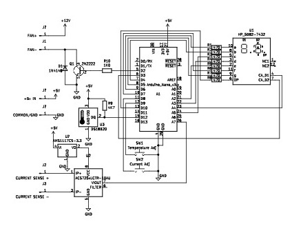
Schematic
Build Notes
I decided to put many of the parts in a 20 pin dip wirewrap socket, mounted right on top of the Arduino Nano. Eight of the ten connections to the LED display need 470 ohm resistors in series, so I replaced the long wirewrap pins of the socket with the resistors (see close-up picture).
Because reading the datasheet before you wire the project is for losers, I wired it up, and then wondered why the decimal point didn't light and why the DS18B20 didn't work. Turns out, pins A6 and A7 on an Arduino Nano can't "do digital". I had to run some jumpers from those device pins to other pins on the Nano to fix those items.
The schematic shows the ACS712 as a discrete part, with a separate voltage regulator to regulate 5v down to 3.3v. In reality, I'm using an ACS712 module with a "Grove" connector on it, so I didn't source the regulator separately. If you use the discrete parts, make sure you follow the data sheet for use of bypass capacitors.
Downloadable Documentation
Zip file of code and schematic
FAQ
Q. Will you make one for me?
A. No, I'm retired and so not interested in a job.
Disclaimer/Warning
This is just my documentation for my build. I don't claim that building this is safe or recommended.
Soldering irons are dangerous, be careful. Oh, and don't eat the solder.
William Dudley
November 14, 2021


 Views
Views