Headlight Modulator for Motorcycle, in the United States
Unhappy with a headlight modulator I purchased, I decided to make my own. Even though it would be a trivial programming project to use an Arduino Teensy or similar to do this, I decided to do it the "old fashioned" way, using a 555 timer. The 555 is a clever chip; not only will it supply the oscillator for the flashing effect, it has a reset pin that can be used to force the output to a known state (low) when (other circuitry tells it that) it's dark outside. Thus the headlight will be steady "on" after dark, flashing in daylight. The 555 is happy to run directly off the nominal 12 volt vehicle electrical system, so no voltage regulator is needed. The 555 is almost immune to electrical system noise, so no worries about your Arduino code going off into the weeds if there's a spike from the electrical system.
The first photo shows three boards from OSH Park; one bare (as it comes from OSH Park), one stuffed, and one stuffed and covered in heat shrink for installation on my motorcycle (inside a fairing). These are an earlier revision that lacks R11 and R12.
Note: Click on the pictures to embiggen.
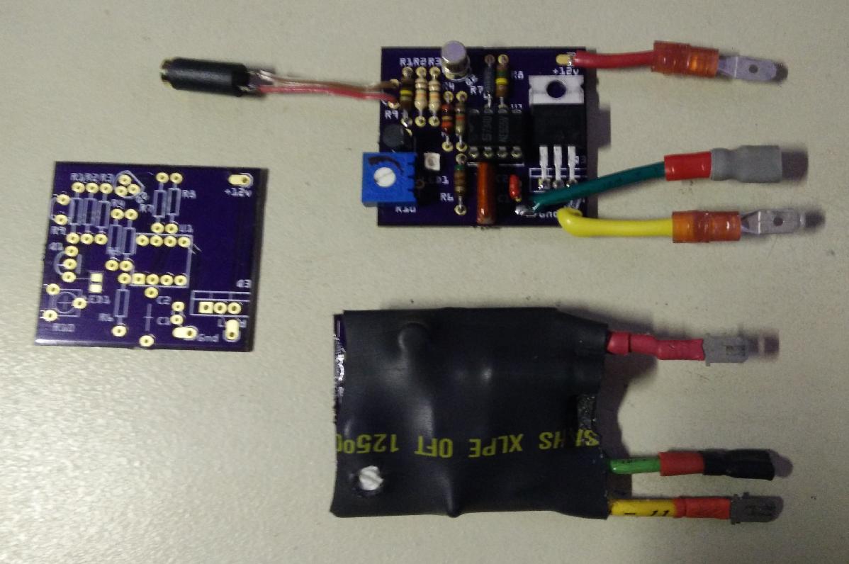
The boards, bare and assembled. The photo resistor plugs into the black jack (cylinder) connected via the red/brown pair. The jack for the bottom right board is hidden under the heat-shrink.
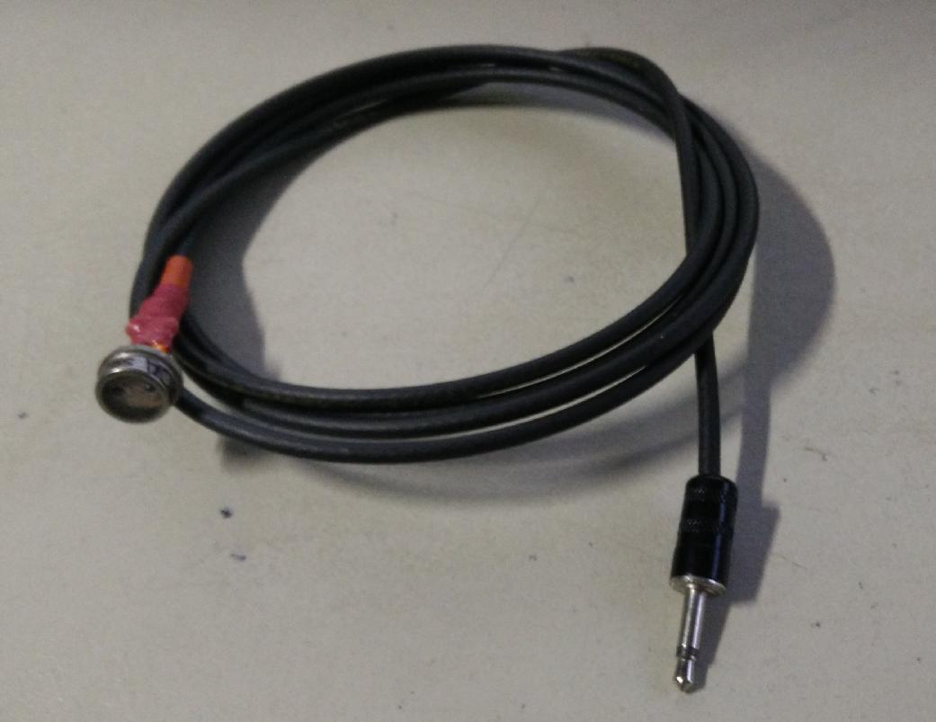
The photo resistor assembly
I designed the circuit on the breadboard, and then documented it using fritzing.
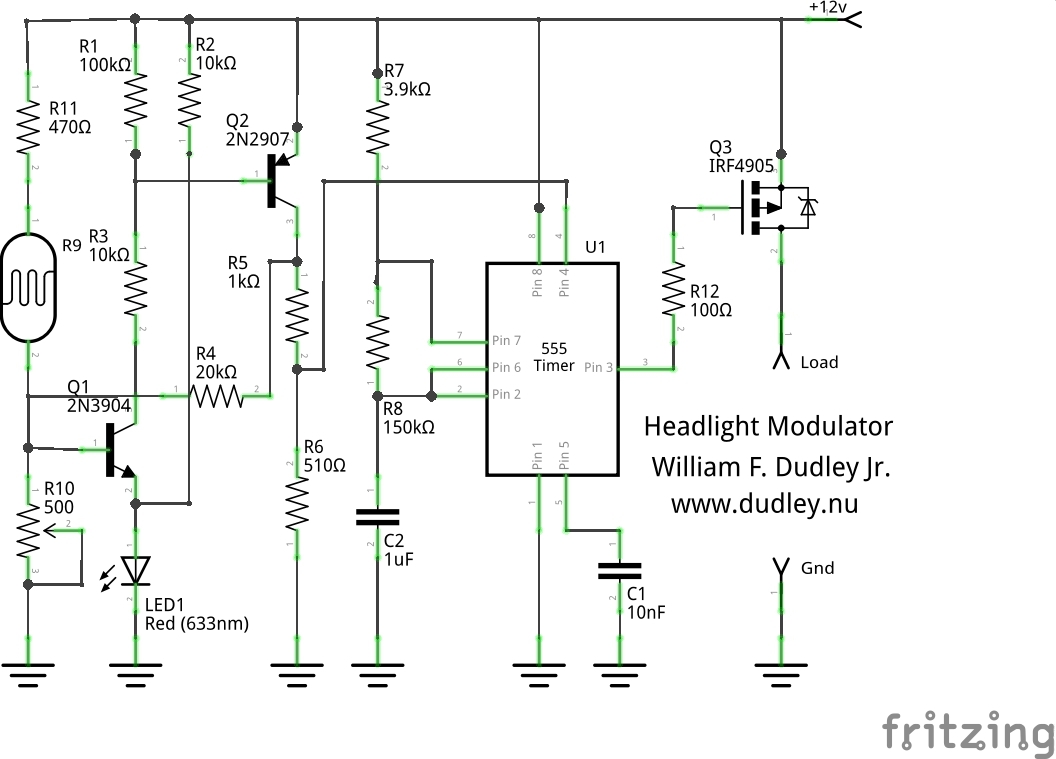
Circuit Description:
Note: this circuit is for a DC, negative ground motorcycle. This shouldn't be a problem, most of you have probably never seen a positive ground motorcycle, but in general, beware British motorcycles made before about 1980, and also some (again, old) motorcycles and scooters had AC lighting systems, and they won't work with this either.
The 555 is configured as a "nearly" square wave oscillator, with R7, R8, and C2 controlling the frequency. The frequency must be about 240 +/- 40 cycles per minute, or about 4 Hz according to the US law governing headlight modulators. The reason that the output isn't a perfect square wave is that the charge current for C2 is through R7 and R8, but the discharge current is only through R8, so C2 discharges faster than it charges. The closest to 50% duty cycle will be achieved when R7 is small compared to R8, but if R7 is too small, then R8 will pull too much current from the power rail when it's discharging C2. 3.9KΩ vs 150KΩ says that the duty cycle error only amounts to 2.5 percent, so duty cycle is close enough to 50% for this application.
Pin 5 of the 555 allows modulating the 555, and we don't need that, so we just hang a 10nF cap on pin 5 as recommended by the data sheet.
The output of the 555 isn't robust enough to drive a headlight, so we use a P-MOSFET (Q3) to do the switching. The chosen MOSFET has an RDSon of 0.02 Ω or 20 milliohms, so it barely gets warm powering a 5A headlight filament. It also has a max drain current (Id) of 52 Amps, so it'll handle pretty much any headlight you care to use on a motorcycle. (Power = I squared R, so for the MOSFET is 25 * 0.02 = .5 watt, which results in negligable heating for a TO-220 package.)
R12 is there to prevent parasitic oscillations by Q3.
The rest of the circuitry is there to sense daylight and switch the modulator to "constant on" when the sun isn't out.
R9 is a cadmium sulfide photo resistor. I have some old ones in my junkbox, I used those. The resistance on these varies from a few hundred ohms in bright light to a hundreds of thousands of ohms when dark. Pin 4, the reset pin of the 555 timer, needs to be high to allow the 555 to oscillate, or low to force the 555 output (pin 3) to be low (0V).
We can't just hook the photo resistor (R9) between pin 4 and battery, because there is a particular set of voltages on pin 4 where the 555 output will stay high, which would mean the headlight would be off. This means that if lighting conditions were just right, the headlight would go entirely dark! So we have to prevent pin 4 from ever staying in this "no man's land"; it must either be at battery voltage or at zero volts.
Q1 and Q2 make up a schmitt trigger (or an amplifier with hysteresis). This means that, as the input voltage changes, the amplifier output will "snap" past a region of middle voltages, both as the voltage rises and as it falls.
You can use any small signal BJTs for Q1 and Q2; I just used what I had in my junkbox. As long as the BVceo is greater than 16 volts (max volts expected from automotive charging system) any decent NPN (Q1) and PNP (Q2) transistors should be fine. The choice for Q3, an IRF4905, is critical; it needs to be carry current of 5 or more amps, and it needs to have a very low Rds-on so it doesn't get hot. These are cheap, however, and readily available (I bought mine on eBay). Do not substitute another MOSFET unless you find one with a lower RDSon value.
The input voltage to the amplifier is set by the voltage divider of R9 (the photo resistor) and R10 (a trim pot). LED1 is used to bias the emitter of Q1 at about 2 volts, so that the voltage where the amplifier starts to switch is at about 2.5 volts (LED voltage plus base-emitter drop of Q1). When Q1 turns on, it supplies base current to Q2 via R3. R1 is there to make sure Q2 is off when Q1 is off. R2 supplies a little bias so that LED1 is always on, at least a little bit, so that Q1 emitter always has a reference.
R11 is there to limit current when in the brightest sunlight, and to prevent battery shorts to ground if the photo sensor cable is damaged and touches ground somehow.
When Q2 turns on, it pulls pin 4 up to 12v via R5. When Q2 is off, R6 pulls pin 4 to ground. When Q2 is on, it also supplies current via R4 to the base of Q1. Because R4 is large compared to R9 and R10, this is only a small effect, but it is enough to rapidly pull Q1's base up (or down) enough to switch pin 4 of the 555 through the "no-go" region, so that the 555 is either "oscillating" or "reset", and never "indeterminate".
Make your own
Fritzing design file is here.
Fritzing board files in a zip file are here.
Installation
Again, remember, this circuit is only for DC negative ground motorcycles. Also, this circuit will probably wreak havoc with an HID light, and an LED headlight may not like it either. So I'd only recommend using this with an incandescent headlight.
Cut the wire that feeds the high (or low) beam of your incandescent headlight. Connect the "+12v" terminal on the modulator to the wire that fed the headlight filament. Connect the "Gnd" terminal to motorcycle ground. Finally, connect the "Load" terminal to the wire that feeds the headlight filament. Put R9 (extend the leads if necessary) where it can "see" the sun, but not so it can see your headlight or those of other vehicles, either ahead of or behind you. You don't want the headlight to start flashing at night!
Initial Adjustment
Adjust R10 to somewhere near the middle of it's range, and then tune it so that the modulator oscillates when outside on a cloudy day, but does not modulate (the headlight is constantly on) when the motorcycle is under any kind of roof. This should give you a good initial setting for the sensitivity.
US Law governing headlight modulators
In the United States, headlight modulators are legal, and the relevant law is Federal law, meaning no state law can make them illegal. Here's the relevant bits (thanks to Kisan manual for their P-75W modulator):
US Department of Transportation
National Highway Traffic Safety Administration
Federal Motor Vehicle Safety Standards
49 CFR parts 571
[Docket No. 97-57; Notice 1;] Executive Order 12866
s7.9.1 A headlamp on a motorcycle may be wired to either the upper of the lower beam from the maximum intensity to a lesser intensity provided that:
- The rate of modulation shall be 240 +/- 40 cycles per minute.
- The headlamp shall be operated at maximum power for 50 to 70 percent of each cycle.
- The lowest intensity at any test point shall not be less than 17% of the maximum intensity measured at the same point.
- The modulator switch shall be wired in the power feed of the beam filament being modulated and not in the ground-side circuit.
- Means shall be provided so that both the lower beam and the upper beam remain operable in the event of a modulator failure.
- The system shall include a sensor mounted with the axis of its sensing element perpendicular to the horizontal plane. Headlamp modulation shall cease whenever the level of light . . . less than 270 lux.
FAQ
Q How does this design meet the "no less than 17% brightness" spec when the lamp current clearly goes to zero?
A Looking at the circuit, it's obvious that the headlight is supplied with full current, and then no current, and then full current again, ad nauseam. So how does this circuit meet the (legal) requirement that the headlight output never drop below 17% ? The answer is that the headlight filament doesn't have time to cool to "dark" temperature; it continues to emit light for the short time it is off due to the residual heat from the last on cycle. I have not verified this experimentally, but it would be an interesting test.
More on the bulb thermal characteristics: this reference(pdf) suggests that the time constant of a tungsten filament is 10 seconds, so the 125msec off time of our modulator is quite short in comparison. This paper(pdf), specifically figure 4 on (pdf) page 7, show that the bulb never cools down completely when driven at frequencies above 0.1 Hz.
Q My modulator blinks far too fast when the engine is running. Why?
A Your electrical system is noisy, and the noise is "confusing" the 555 timer chip. I had this problem, and solved it by cutting the +12v trace from the input pad to all of the circuitry except the MOSFET. I bridged the cut with a 100Ω resistor (1/4 watt sufficient, I used 1/2 watt). I then soldered an 8μF 20v capacitor across pins 1 and 8 of the 555 timer, with the positive side of the capacitor on pin 8 of the 555. This will filter the +12v supply to the 555 timer and solve the noise problem. In answer to the question "how did I choose 100Ω and 8μF": I guessed. (This Q/A added 2015 03 03.)
Disclaimer
Realize that if you undertake to build and install this, you do so entirely at your own risk. If your headlight fails to work, at night, it could be extremely dangerous. If you only hook the modulator to one of your headlight filaments, you will at least have the other filament in case the modulator fails to power it's filament, but there is still an element of risk.
Track Back
William Dudley
November 22, 2015


 Views
Views