Burglar Alarm System Input Buffers
Here's the schematic of the custom circuitry (click to embiggen):
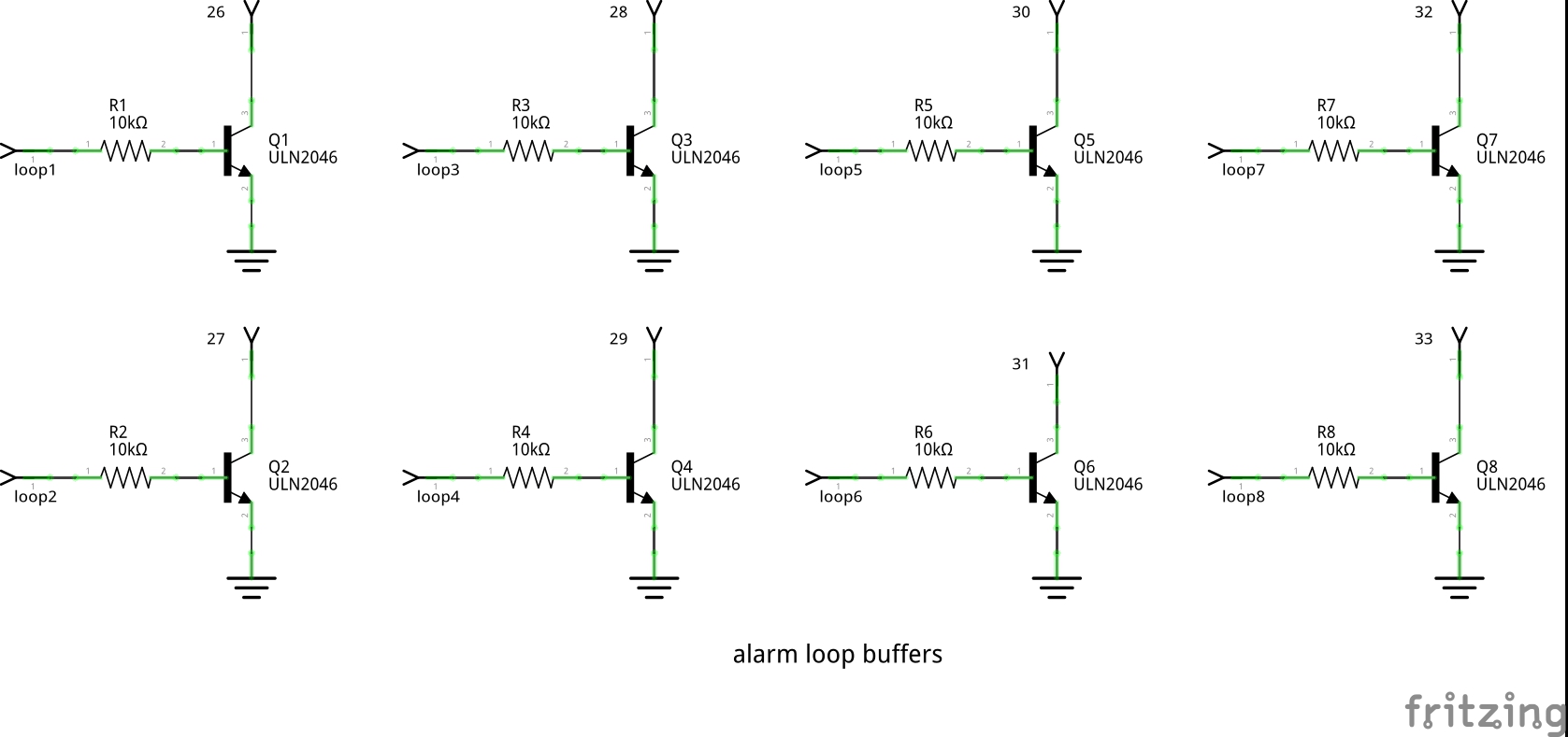
Again, apologies for the schematic, I used fritzing, and it doesn't have a model for a ULN2046 transistor array. Instead, I just dropped 8 discrete transistors on the schematic, so the pinout of the ULN2046 is lost. The circuit is trivial, however. Each ULN2046 has five transistors in a 14 pin dip, so I used five in one package and three in another to get my eight buffers.
The buffers just attempt to isolate the relatively fragile inputs of the Arduino from electrical noise/spikes/etc that might be present on the alarm loops, since the loops run the length of the house. The loops are tied to +12v through a 2.2K resistor, so that if the loops short to ground, the 12v supply isn't shorted out. The loops just supply +12v to the buffer inputs (assuming the loop contact is closed.)
The outputs go low if the loop is closed, high if the loop opens.
More protection could be added by putting zeners across the inputs to the buffers, were I that worried about electrical spikes. A value of 10 to 20 volts would be sufficient.
William Dudley
March 28, 2016


 Views
Views